Bruder Piggyback Forklift Build part 10
I'm going to split the installation of all the electronics into two parts. In this post I'll show all the components I used and some modifications. In the next I'll go over the actual installation..
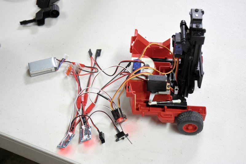
At the end of the last post I mentioned that I hooked everything up and tested to make sure that after all the putting together and taking apart that it would all work properly. This photo shows everything laid out on a table and temporarily wired up as I tested.
[img]
[/img]
Man, what a mess of spaghetti. In this photo you see the following parts: 1 battery pack, 2 ESCs, 1 6-channel receiver, 4 JST connectors, and next to the battery pack a pair of 3 terminal WAGO connectors. Will it all fit?
This is the battery I ultimately ended up using. While 500mAh doesn't sound like much capacity I have found in use that I can easily get a good solid hour of continuous run time out of it. And it fits easily into the space available. I purchased this particular battery from
https://www.buddyrc.com They are an online only RC hobby store located in Columbus, OH. They primarily deal with the airplane/drone crowd but what hobby store doesn't. BTW, if you are looking for a RadioMaster transmitter they are dealers and also carry a wide array of spare parts.
[img]

[/img]
This is the receiver I used in this build. It is a 6-channel DSM compatible unit so it will work with almost any Spektrum radio as well as Open TX radios such as the RadioMaster. This receiver is the smallest 6-channel one that I know of that will take standard servo connectors. The only ones smaller use soldered connections instead of plugs. These receivers also have the advantage of being relatively inexpensive. This one is a bare bones model by which I mean it doesn't have telemetering or a diverity or duplex antenna. I purchased this from BuddyRC also. Be aware if you shop for one of these they come in two basic versions. The one shown is the 'top' connected version. They also make it in an 'end' connected version which is going to be about 1/4" longer and you would also need extra room at the end for the plugs.
[img]

[/img]
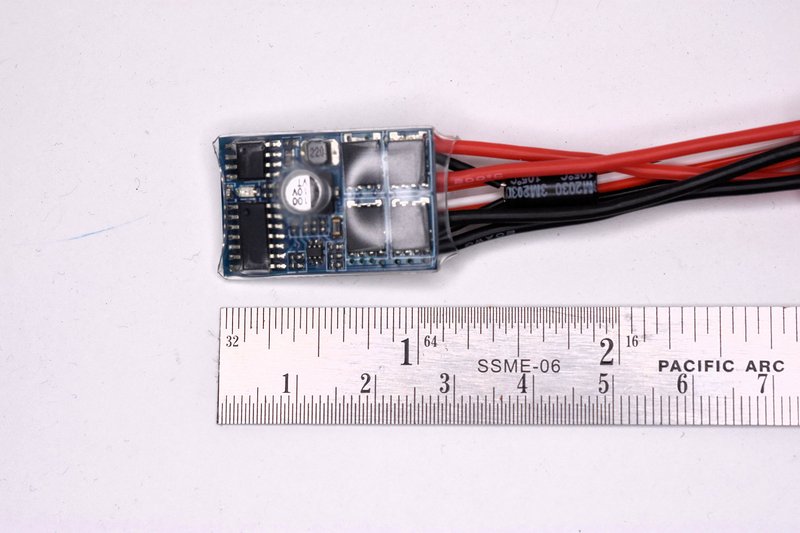
This next photo shows one of the ESCs I ended up using. These are 2S, 10A rated units. They have a 1A BEC and no braking. I originally wanted to go with 3S ESCs but couldn't find any that worked properly or that didn't let the magic smoke out after a few seconds. I really wish there was a source of US made ESCs. These were obtained on Ebay. They are all made in China so I don't think it really matters much which vendor you pick, I'd just look for one who states they ship from within the US. On the right side you can see a large capacitor extending out from the circuit board. This is apparently a new design, and so far, mine have worked well.
[img]
[/img]
I made a few modifications to these ESCs. They came with a switch attached to wire leads to turn the ESC on and off. Since I was going to use a master switch I didn't need the attached switches. And I especially didn't need two switches.
To remove the switches I had to remove the plastic heat shrink that had been put on by the factory. Just use a sharp knife and pare down along one edge of the circuit board and peel off.
[img]

[/img]
Then using a small soldering iron I heated up each blob of solder on the circuit board at each switch wire location on the lower right as shown. When each blob melts just pull the wire free. Don't remove the little blobs of solder.
[img]

[/img]
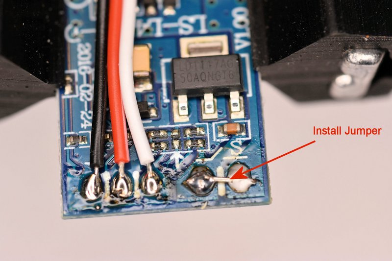
Without the switch there is no way to turn the ESC on. Simple fix, just solder a small jumper across the two pads where the switch wires used to be. I just used a small piece of wire snipped from a resistor. The blobs of solder left behind from removing the switch wires should be enough.
[img]
[/img]
These ESCs are going to be mounted in a plastic body and all the wires on and around them will be insulated. But I still felt it wouldn't hurt any to re-insulate the boards. You could put heat shrink back on like they had originally but I decided to wrap them in Kapton tape. Kapton tape is very thin, very strong and has a very high dielectric or insulting rating. It's also not cheap. But I had a lot left lying around from my early 3D printing days when we used to put Kapton on the build platforms as a surface for the print to stick to. I primarily used it because it was a lot thinner than the heat shrink and I wanted all the spare room I could get.
[img]

[/img]
Since I had two ESCs that were going to be connected to the same receiver the last modification was to remove the red + wire from one of the servos so the receiver would only get power from one ESC.
So, next post I'll finally get to what most of you have been wanting to see. How I put it all the electronics inside the body of the fork lift.