Bruder Piggyback Forklift Build part 11
OK, time to finish this up. Will everything fit inside. Of course, didn't you see my first post? There was some trial and error involved in deciding where to put the components but it actually was easier than I was afraid it would be when I started this conversion. There were a few snags and I'll point them out so you can avoid them.
The first step was to lay in a length of two conductor cable for the battery power supply as shown. It has a JST connector on one end and is longer than anticipated and will be cut to final length later. The red wire will go to the master switch under the operators seat and the black wire will actually get pulled back about to the center of the wheel housing for the negative return to the battery.
[img]
[/img]
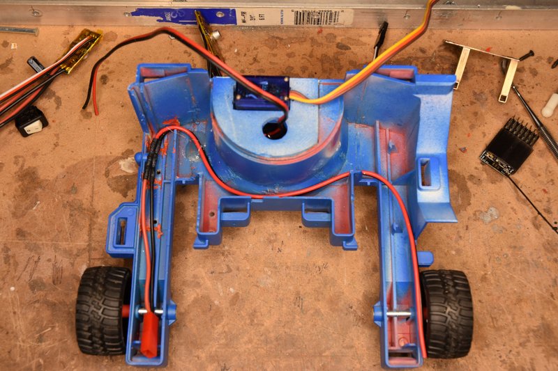
The first component I mounted was the ESC for the drive motor. I simply hot glued the ESC to the back right side of the rear wheel housing as shown below. The large capacitor on top was just pushed over so it laid on top of the wheel housing.
[img]
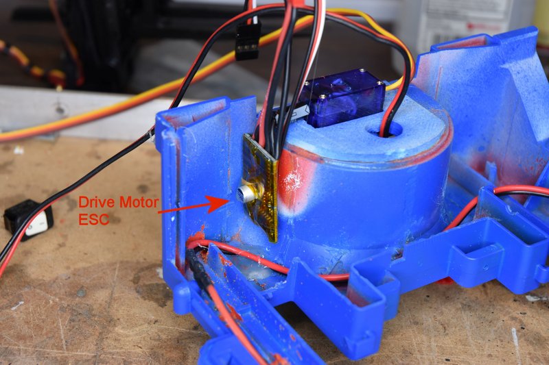
[/img]
So logically the second ESC for the lift motor should go on the other side of the wheel housing. So that's where I mounted it and again bent the capacitor over to lay on the wheel housing.
[img]
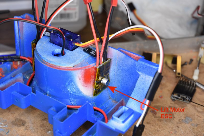
[/img]
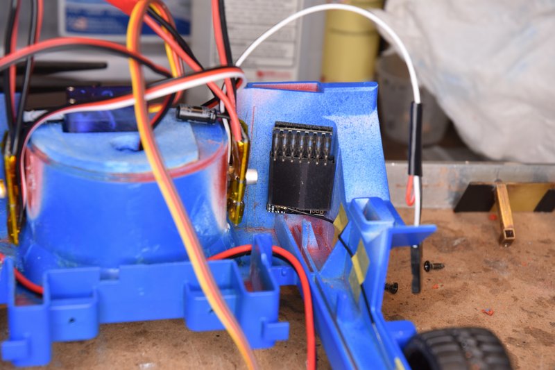
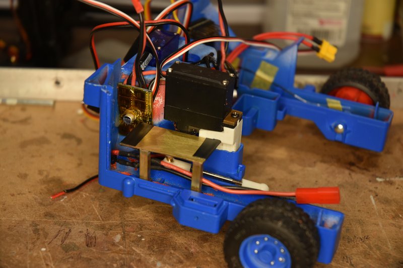
Using a piece of servo tape I mounted the receiver in the position shown. I placed the terminals for the servos on top so they would be easy to get to and figured that would give me room underneath to coil up excess servo lead. I bent the antenna wire to run along the side of the left wheel arm and taped it in position.
[img]
[/img]
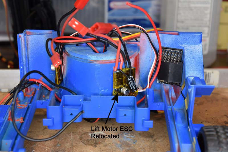
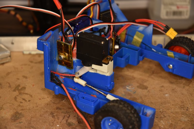
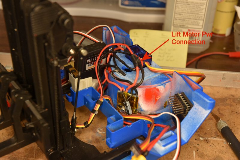
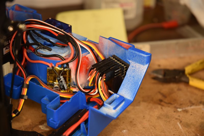
SNAG #1 - If you have been following this build and seen the 3D printed parts I've used from Thingiverse, have you wondered why the steering servo mount is straight instead of curved on the left side? It' because part of the top body section hangs down over the left side of the wheel housing in this area and there isn't enough clearance for the printed part. I tried assembling the top and bottom body sections together at this time to check fits and clearances and found that the capacitor on the lift motor ESC would not fit. If fact none of the wires sticking up from the ESC would fit. I think I got so used to just working on the lower body section that I forgot about this clearance issue. So after some study I removed the ESC and remounted it to the position shown below. I also mounted it lower so the wires wouldn't get in a bind with the top part of the model and bent the capacitor leads down over the front of the circuit board.
[img]
[/img]
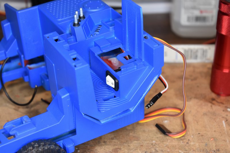
Next I mounted the master switch into the hole made previously in the top body section. In this photo I had placed the top body back into position to check clearance from the back of the switch to the receiver. Good reason for removing the drivers seat.
[img]
[/img]
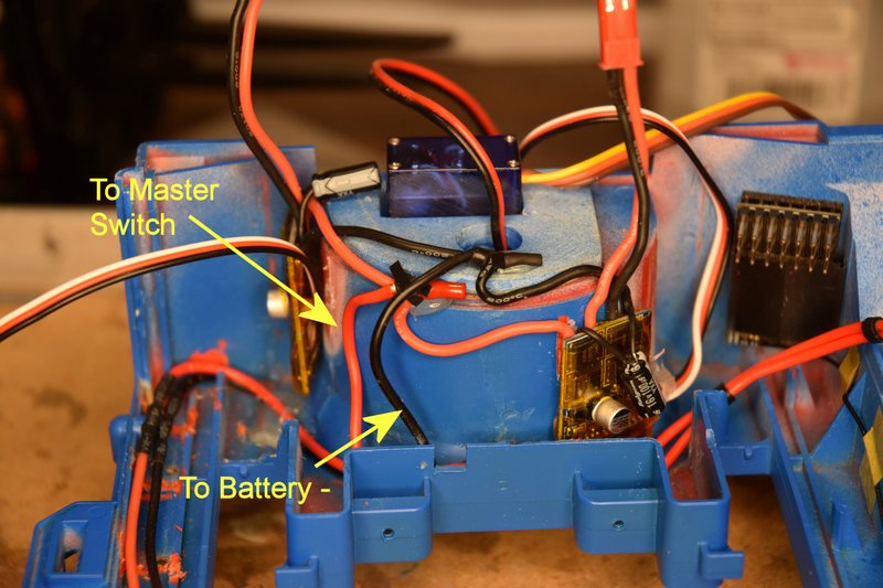
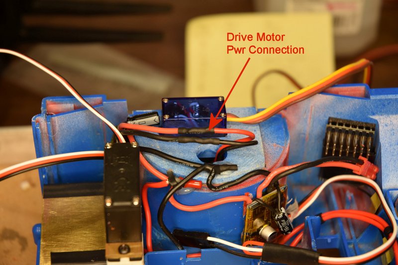
I wanted to be able to completely separate the top body from the bottom for maintenance and repair work if ever needed. So I installed a XT30 connector as you see. I used this connector because it was the smallest two conductor connector like this I had on hand. The JST connectors are longer when assembled and I though they might get in the way. While the XT30 works I now wish I had taken the time to find something smaller. This doesn't need to be a polarized connector either. The switch is just in series with the positive battery lead. You can also see the second red wire added to go from the switch back to about the center of the wheel housing.
[img]
[/img]
I had wanted to use the WAGO connectors to make the power connections. I really like those things but they were just a little too big to fit in the space between the front of the wheel housing and the front wall of the lift. I could have maybe put them at the bottom backside of the lift but would have then had to splice extra wire to the ESCs. Didn't feel like doing that much extra work. So I simply twisted the ends of the black wires and red wires together and soldered them. Then insulated the ends with a piece of heat shrink and a little tape. These wires are a little stiff so I held them in place with a couple dabs of hot glue.
[img]
[/img]
Reinstalled the mast platform retraction servo.
[img]
[/img]
Followed by the battery platform. I covered the edges of the platform with a couple of layers to electrical tape to protect the wires from possible cutting.
[img]
[/img]
Next was to cut to length and splice the power leads from the drive motor to it's ESC. Solder and heat shrink tube to insulate.
[img]
[/img]
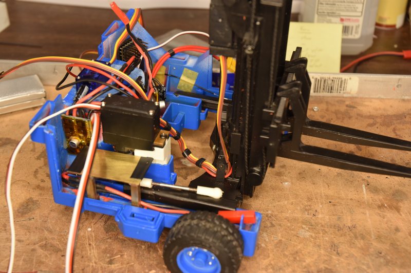
I then wrapped narrow pieces of tape around the tilt servo leads and lift motor wires on the mast assembly to bundle them together. Place the mast assembly back into place on the lower body and connect the servo linkage.
[img]
[/img]
Then the lift motor leads and and ESC leads were trimmed to length, spliced and heat shrink.
[img]
[/img]
Next is to run the servo and ESC control cables to the receiver. I won't show all of these being run. I ran the cables from the drive ESC steering servo and mast retraction servo across the top of the wheel housing to the receiver. The lift motor ESC and tilt servo cables were run across on the bottom of the body to the receiver. Each cable needed to be shortened to some degree so I wouldn't have a huge mass of wires under the receiver. So I ran one cable at a time starting with which ever cable I had assigned to channel 6 on the receiver. And then channel 5 and so on. I'm not using channel 2 so it's open as well as the battery port since power is coming from the drive motor ESC.
[img]
[/img]
OK, as usual the web site is telling me I talk to much. Have to break this post here and will continue in the next.