
 |
|
|||||||
| Highway Trucks and Trailers On road trucks and trailers single and twin axle trucks. |
 |
|
|
Thread Tools | Display Modes |
|
#1
|
|||
|
|||
|
About two years ago I was watching a video clip of a RC truck meet in England. If I remember correctly it was in a link posted by Bo Wallen of his trip there to the UK Nationals. Part way in there were a few seconds showing a small "piggyback" type forklift loading a flatbed trailer. I was really fascinated by this little forklift. They are very common where I live and I had never seen a working model of one before. Here is a screen capture of the forklift from the video.
[img] 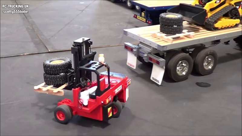 [/img] [/img]I thought it would really be neat to get one of these and see if I couldn't convert it to full RC. I really had no idea where to start. It appeared to be sort of toyish in looks so I suspected it might be made by Bruder. Sure enough, about two months later I was in a Tractor Supply store and happened to walk down their toy aisle. Out of the corner of my eye I saw a Bruder Mack box truck labeled for UPS and hanging on the back of the truck was the little forklift. [img]  [/img] [/img]Apparently the forklift is only sold as a set with another truck and I didn't feel like spending $100 just to get the forklift, especially as I had no idea if I could do the conversion. I went to Bruder's web store and found that the forklift was listed as a 'spare part' for the UPS truck and could be purchased individually that way. Price for just the forklift was $21. That was cheap enough that I bought two of them, one to chop up and experiment on and figure out how to do the conversion and then a clean one to do the final version with. If I couldn't make it work I wasn't going to be out much money and would have the fun of trying. I started by searching the internet to see if I could find examples of other conversions and see if I could get some ideas on how to proceed. Ideally I would find a build article or 'how to' from someone who had done the conversion. No such luck. After many, many hours of searching I was only able to find a few photos and very short video clips of a couple of these in action. I was able to get a couple of ideas on how to build but was still left with a lot of questions. The other thing I noted was that some of the conversions were sorta crude. If you look at the photo of the forklift from the video clip you can see that what appears to be a battery pack and other parts are sticking out of the body in several places. I didn't want that. When I do a Bruder conversion one of my primary goals is to keep the body looking as much like the original as possible. If you look at one of these Bruder forklifts it is very apparent there is not much room inside for a battery, motors, servos and all the other electronics needed. That would be the biggest challenge. After months searching and looking at the model I was just about to decide to just tear into it and see what I could do when I finally hit some pay dirt on the internet. Last winter when searching again I came across a posting on the Bruder Facebook page showing a conversion that I thought looked really good. The author posted a number of photos showing some of the details of his work and that was the info and inspiration I needed. He also said that he would post his 3D print files on Thingiverse if anyone wanted them. I won't list his name as I don't have permission but you can find the article and print files by searching 'Bruder UPS forklift' on both Facebook and Thingiverse. Using this information as a start I was able to create what I think is a very nice, fully RC controlled model of this forklift. If there is any interest in this conversion process I will write up a series of articles on how I did mine. This will be some work on my part and will take time. If you want to see how I went from this: [img] 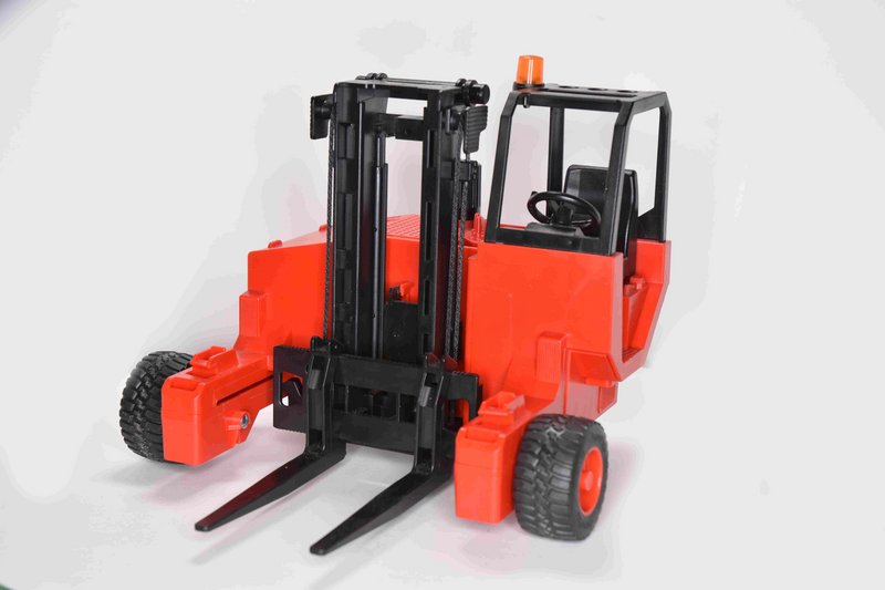 [/img] [/img]to this: [img] 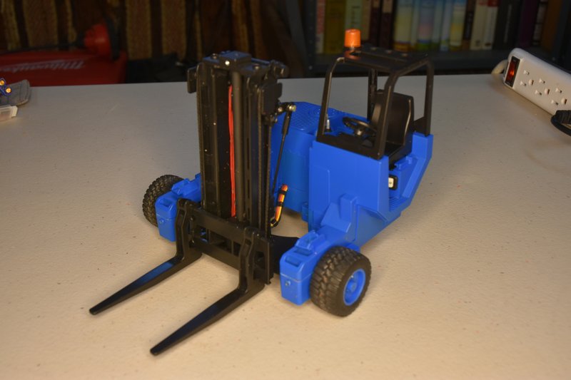 [/img] [/img]Let me know. Yes, it's now blue because a) I had 3D printed parts that needed to be painted and I don't know of a good paint match for Bruder's red, b) a lot of the piggybackers I see around here are blue, and c) I really like blue. |
|
#2
|
|||
|
|||
|
Ab so Lootly... I have the UPS set, got it at a toy show for $50... The forklift is on my "to do list" I think somebody here did this one but I can't remember who.... and I know Frizzen has done other types...
Lets see how this goes... |
|
#3
|
||||
|
||||
|
Oh wow, that's gonna be really cool to see getting converted!!!
How's the stability? I mostly see that type hanging off of flatbeds delivering building supplies. Did you build the ability for it to stow onto the truck for transport?
__________________
What do ya mean "Cars are neither Trucks or Construction"? It's still scale, and i play fairly well with others, most of the time... |
|
#4
|
|||
|
|||
|
Oh, write away! Conversions are in many ways much harder because, as you note, the thing is designed for looks and not to fit all the stuff inside that a full RC needs.
Heck, the only conversion I've done is from a vintage wired RC to modern wireless (admittedly with some other work), and getting the battery and whatnot to fit was a nightmare. I've gotten spoiled doing scratch builds and adjusting the shape or dimensions as required to get the desired components to work. Also, as obvi you're aware, forks are bloody complicated. I did one and while it works well enough, the scale and appearance suffer a bit for that. Finally, this one looks like the tines are adjustable-spacing, which was a luxury I couldn't squeeze into mine. I had to have fixed-spacing tines on a carriage that shifted side-to-side. I'd love to see how you made all the moving parts ... well, move  -- A
__________________
I mean, how hard can it be? |
|
#5
|
|||
|
|||
|
Yes it is capable of lifting itself up. One of the first things I tested when I got it fully assembled. I will have to modify the rear of my flatbed trailer so that it can haul it.
|
|
#6
|
|||
|
|||
|
Yes the Bruder has adjustable tines but they have to be moved manually. And yes, I will start posting my build of this in the next day or two.
|
|
#7
|
|||
|
|||
|
Bruder Piggyback Forklift Build part 1
OK, a few caveats first. Like any of these Bruder conversions there are a number of ways to do it. This is the way I did it with the parts I had, and I'm sure there are other/better ways. Experiment and have fun. Post up your builds if you do something different. Second, I will not build one for you and I will not provide parts. As stated in my first posting I used the Thingiverse parts as the base for my build. And while I ended up only using a few of those parts the others that I made were based on them. And while I am fortunate in having a fairly well equipped shop to work in I think all the parts could be made with hand tools and/or a simple 3D printer. Lastly be aware of the limitations of this model. This is a lightweight toy. Even with all the RC gear stuffed inside it will tip over very easily, especially if the mast is all the way forward. I just wanted to be able to load my flatbed with pallets holding four scale oil drums. These weigh about 5.3 ounces or 150 grams. My model will handle this but I had to add some lead weight to the rear wheel to do so. The mast and forks will also bend to some degree under load. So you are not going to be able to lift the larger loads that other RC forklifts can but it is still a great build. Lets get to it The first part, and often the hardest with these conversions, is simply taking the dang thing apart. This forklift is no exception. Bruder intended these toys to hold together through all the beating a child could give them. (EDIT: moved this paragraph here from part 2 because if you don't do this first you can't take the model apart) The first step, if you haven't already done so is to remove the rear drive wheel from the model. This is easily accomplished by simply cutting the top knob of the steering control off right where it meets the upper body. [img]  [/img] [/img]The drive wheel and support mount should fall right out the bottom. Carefully pull the wheel/tire off its axle and set it aside. The rest of the mounting will not be used and can be discarded. I used several small and thin screwdrivers and picks to pry locking tabs back and try to pull a joint open. I started at the front of one arm and just worked my way around using toothpicks to shove into open joints to keep them open. Go slow and easy and it will come apart. One good thing about this model I found is that the wheels will pull off their axles fairly easy without being damaged. [img]  [/img] [/img]I figured that I was probably going to have to put this thing together and take it apart a lot of times before getting done and I didn't want to go through that disassembly headache every time. Plus making it easier to do maintenance/repairs in the future. So first thing I did was to take every locking tab; [img]  [/img] [/img]and sand them flat. [img]  [/img] [/img]Then to hold the model together I drilled a hole through both top and bottom pieces at every location where there was a locking tab and installed a #2 sheet metal screw. [img]  [/img] [/img]DO NOT drill/screw the two locations in the front center as I have here. I didn't think of it at the time, but once the mast assembly is put back in place you can't get to these. Don't need them, the other six screws are plenty. Prying the tabs from underneath I then removed the ROPs and driver seat. [img]  [/img] [/img]Now is probably a good time to go ahead and start cutting away a lot of the internal plastic that has to be removed to make room for all the RC parts. Keep in mind that I removed plastic at different times during my build as I was working on trying to fit a specific component. You will see in future photos this progression of removal. But you can go ahead and remove almost all of it now. The body remains quite stiff and strong so there is no real risk of breaking it without all it's internal bracing. [img]  [/img] [/img]On the bottom half you can remove all the parts with the green outline. A Dremel or similar tool is the easiest way to do this. Just cut/grind away everything until you reach a flat surface. Go slow and easy to avoid the tool kicking away and damaging something you don't want cut. The area outline in yellow you may want to hold off on for the time being. I had to lower this area to clear the servo arm I used to move the mast assembly in and out. Depending on your servo/mount combination you may not need to. Finally the two parts outlined in white. Be careful not to cut/grind/damage them in any way as these are the rails the mast assembly slides on. [img]  [/img] [/img]On the top half of the model cut/grind away all the areas outlined in green down to flat surfaces they are attached to. Again, you may want to hold off on cutting away the cross shaped part outlined in yellow. The end of this part is a guide that keeps the mast assembly from tilting forward under load. Unfortunately this area is also about the only place you can fit a battery pack. I ended up having to remove this part and found it's loss to not be a problem. Comparing my finished model to the the original I found that the amount of up/down movement in the mast assembly is about the same. Moving to the outside of the model, cut off and sand smooth the mast grabs at the front. [img]  [/img] [/img]Need to clip away a bit where the right arm extends from the body to clear the area where the mast extend/retract rod will have to be. You may want to wait on this till you have your servo and control rod in place so you can see exactly where and how much to remove. [img] 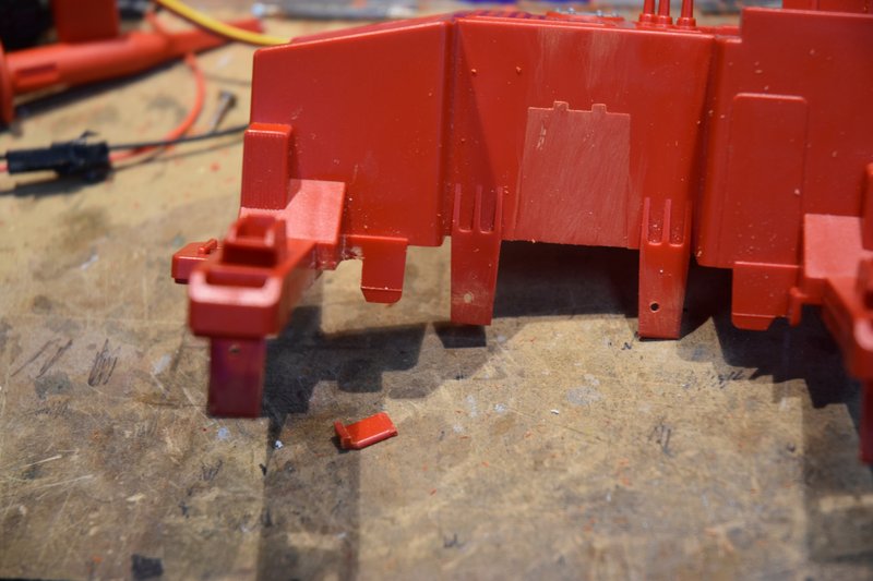 [/img] [/img]I had to cut an opening as shown for the wiring from the mast lift motor and tilt servo to enter the body. Again you will probably want to wait until you know exactly where and how big to fit your build depending on your components. [img] 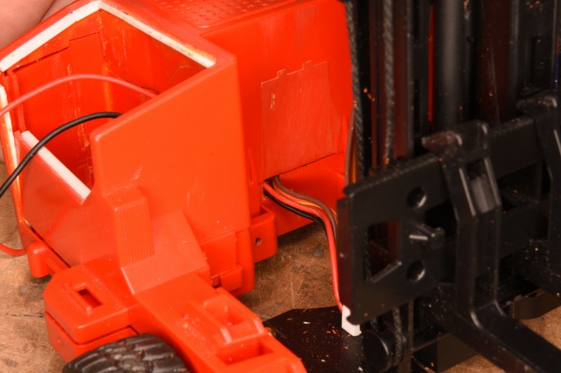 [/img] [/img]Lastly, for this posting, I like to install a master switch to control all the power on my models. I typically use a miniature 6A rocker switch. I thought that a good place for it would be under the operators seat and so cut the appropriate sized hole. [img]  [/img] [/img]That's all for this time. Have fun. Last edited by Zabco; 09-02-2021 at 02:50 PM. Reason: Got step out of sequence |
|
#8
|
|||
|
|||
|
Good point.. you got to know your toys limitations.... people forget that sometimes...
I've looked at the files for this on Thingiverse but haven't done anything with them yet.... Conversions are fun when you take a static toy and make it work.... |
|
#9
|
|||
|
|||
|
Bruder Piggyback Forklift Build part 2
I had to wait for a bunch of the parts I needed for this build to arrive so decided to start by making and installing the rear drive and steering assembly. This assembly requires printing out the 'UPS_drive_motor_arm' and 'UPS_steering_mount_V2' parts from the Thingiverse files. In this posting I am just going to cover the installation of the steering mount. This photo shows the steering mount and battery cover on the 3D printer build plate. [img] 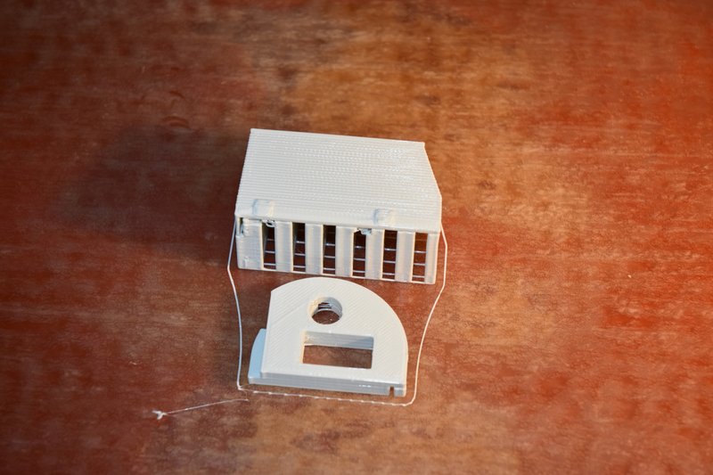 [/img] [/img]You will note that the steering mount is not symmetrical and the slot for the servo is not centered. How to install this part and keep the servo axis centered in the forklifts wheel well? Here's how I did it. The mount is designed to use a standard 9gr micro servo that is inserted into it's mounting slot from the bottom. You could just install the servo and eyeball the placement but I wanted to ensure that it was dead center. This photo shows the parts I used. [img] 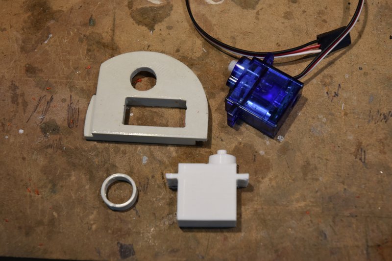 [/img] [/img]At the top is the steering mount and a micro servo. In the bottom is a 3D printed copy of the servo and a ring. You don't need the servo copy but I already had some left over from another project where they were used to help design the layout of hydraulic components. Using the copy servo kept dangling wires out of the way. The ring was sized to take up the difference in size between the steering mount hole in the back of the lift and the neck of the servo. The ring, servo and steering mount were put together and then placed over the hole in the back of the lift. [img] 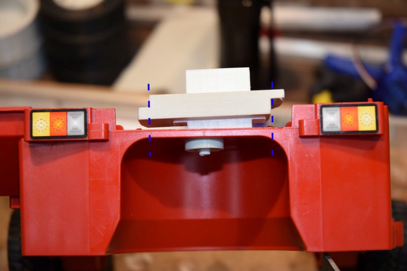 [/img] [/img]This ensured the axis of the servo was centered in the wheel well. Using a straight edge I then transferred the location of the steering mount sides down to the lift body. I then used a small square to draw out the straight cut lines on the floor of the lift. [img] 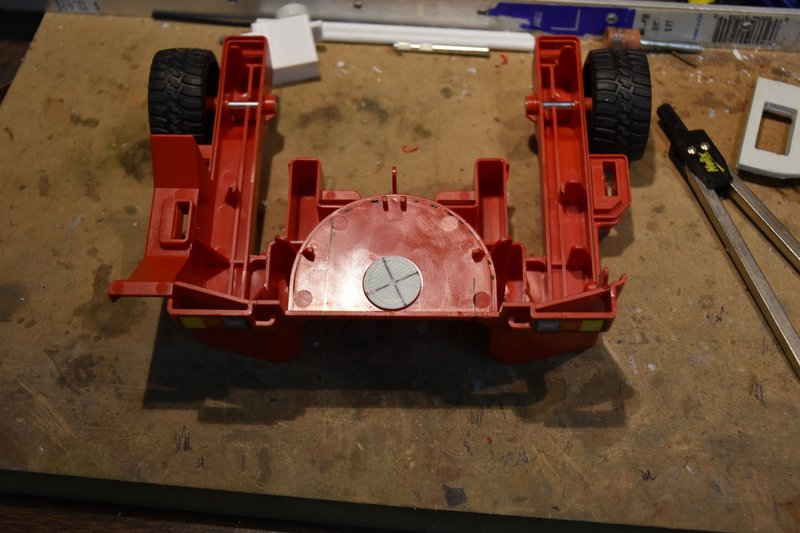 [/img] [/img]Next I printed a plug sized to fit in the hole of the lift with a center mark drilled in it. This is used to hold one arm of a pair of dividers or a compass set to match the radius of the curved part of the steering mount. The divider or compass can then be used to scribe the curve that needs to be cut out. This next photo shows the resulting guide lines for the cuts that need to be made. [img] 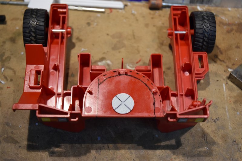 [/img] [/img]The base is then cut out using whatever method you prefer. I used a short Xacto saw blade on the straight cuts and a length of thread to cut out the curved portion. [img] 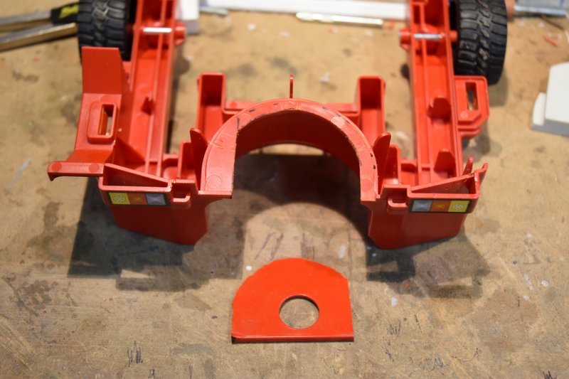 [/img] [/img]The printed steering mount can now be glued in postion as shown below. I used a two part epoxy. [img] 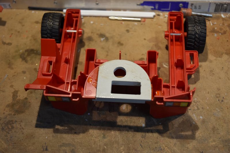 [/img] [/img]The reason the curved part of the mount is on top of the floor and the straight part is underneath is because there is a portion of the top half of the lift that hangs down and when installed will almost touch the floor just to the left of the mount. More about this later on. After letting the epoxy cure fully, I installed the servo and then placed the upper half of the model in place to check on fit. As can be seen in the next photo the thickness of the mount is thicker than the floor section removed was and will not allow the two halves to come fully together. [img] 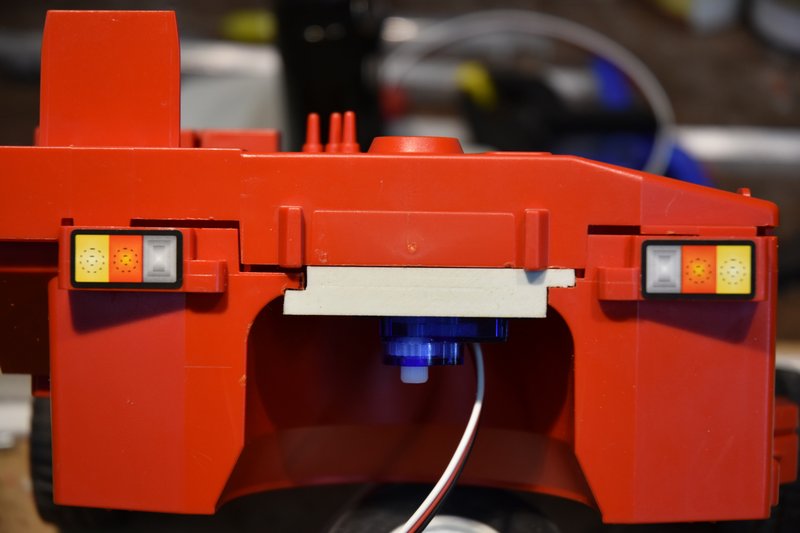 [/img] [/img]Simple fix, just mark on the upper half where the edges of the mount hit and then cut/file/sand a notch just deep enough that the two halves will come fully together. [img] 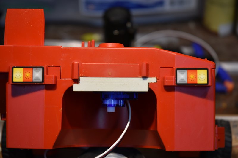 [/img] [/img]That left a nice big gaping hole in the top of the lift where the manual knob used to be. [img] 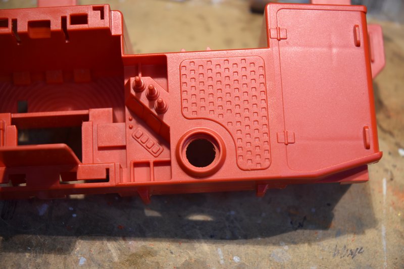 [/img] [/img]Again, a fairly simple fix. Measure the diameter, transfer to a flat piece of styrene and cut out a disc to glue in place over the hole. [img] 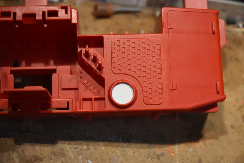 [/img] [/img]And then file and sand the rim down flush with the disc. [img] 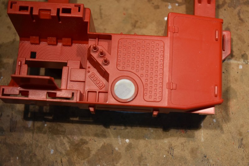 [/img] [/img]Just having that plain flat disk there kind of bothered me after looking at it for awhile. On a real lift why would it be there? Well maybe we can make it look like an access plate for maintenance. I used to be heavy into model railroading years ago and still have a lot of modeling parts for rail cars left over (never throw anything away, right). Looking through that stash I came across some nut/bolt castings that I thought would dress up that plate and make it look like it could be removed. Measured the outside diameter of the plate rim and printed up a disc with evenly space holes to use a a drilling template. [img] 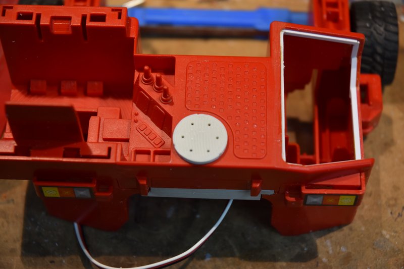 [/img] [/img]Drilled holes of the proper diameter to match the castings. Inserted the nut/bolt casting into place and glued from the backside with CA. They are square headed nuts but they are so small that its not really noticeable and I think made a big difference in the appearance of the model. [img] 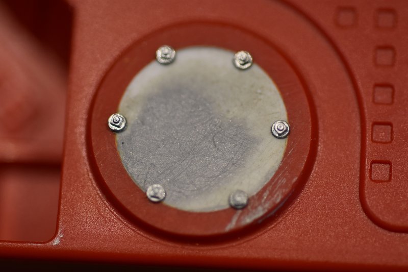 [/img] [/img]That's all for this post. I the next one I'll cover the drive motor assembly and installation. Last edited by Zabco; 09-02-2021 at 02:52 PM. Reason: Out of sequence |
|
#10
|
|||
|
|||
|
Bruder Piggyback Forklift Build part 3
In this part I'll show how I assembled the steering and drive motor assembly. I used a common N20 motor/gear box. The one I used was rated 12V and 100rpm. I used a 12V rated motor because I initially was going to use a 3S LIPO battery and ESC. If you haven't already you need to print out the 'UPS_drive_motor_arm' from the Thingiverse files. The N20 motor was a perfect friction fit in mine and required nothing else to hold it in place. Sorry, don't have a photo just showing how the motor fits into the arm but it's pretty obvious once you see the part. There is a recess in the top of the arm that fits over the shaft of the servo and a standard servo arm screw is used to secure it in place. I had a problem with the arm slipping on the servo and not staying in place. To fix this I put the arm in my small milling machine and cut a flat bottom hole with a 1/4in cutter. [img] 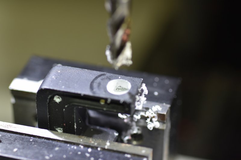 [/img] [/img]I then took an old, damaged servo arm I had and cut the center splined hub out and epoxied it into the hole I just milled. [img] 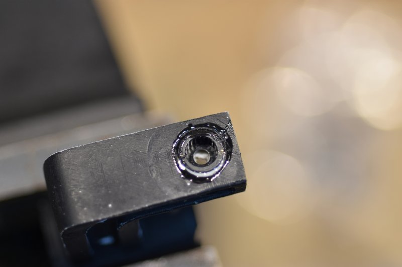 [/img] [/img]This locks the arm to the servo shaft and no more slipping. Next was to mount the wheel/tire to the motor shaft. The shaft from the gear box is 3mm in diameter and is a loose slip fit into the hole in the hub of the wheel. The hub though is longer than the motor shaft so that when placed on the drive shaft the tire is not centered under the servo shaft. To fix this the hub has to be shortened. To determine how much to remove I took a thin piece of plastic, placed it alongside the motor shaft and marked it to use a length gauge. [img] 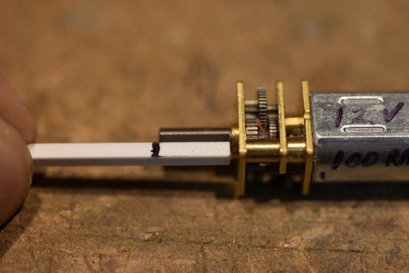 [/img] [/img]There are a number of ways to cut back the hub, I used my small mill after clamping up the wheel/tire in a 3-jaw chuck. [img] 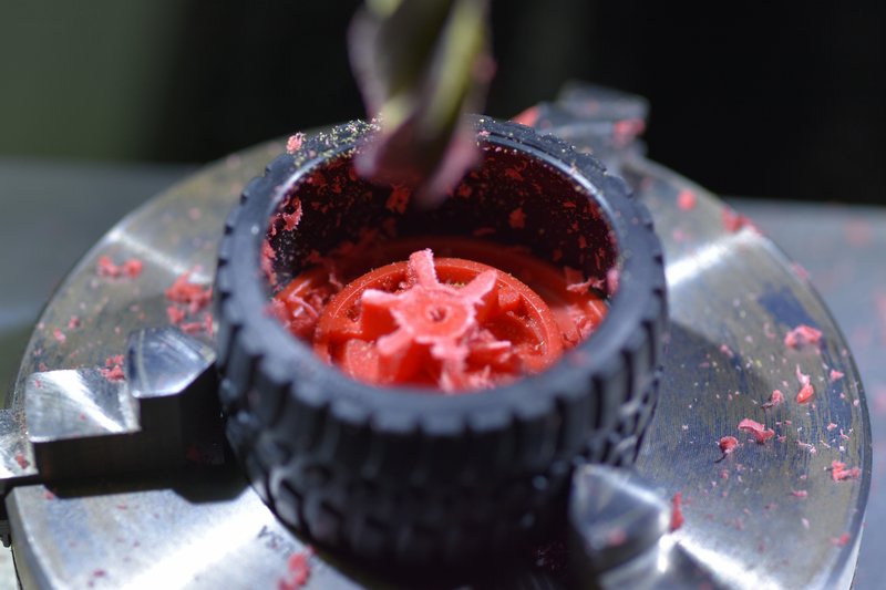 [/img] [/img]Then I would mill off a little bit of the hub, check the remaining length with the gauge. Kept repeating this until the mark on the gauge was fully exposed. [img] 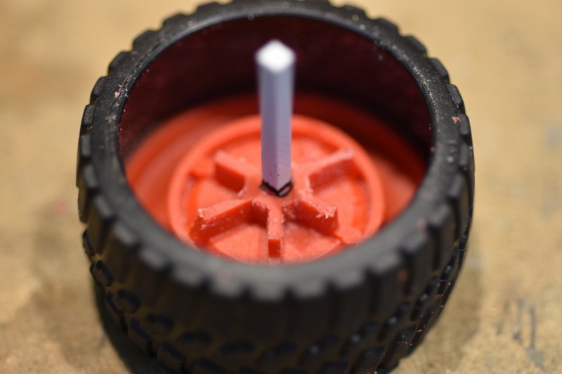 [/img] [/img]This ensured that the remaining hub was just slightly shorter than the length of the motor shaft and would not rub against the gear box. The tire ended up being almost completely centered under the servo shaft. It's just a little off but not enough to be a problem. If you want it to be completely centered then you could remove a little bit off the end of the drive shaft and shorten the hub just a little more. If you try and drill the hub a little deeper I think you have a good chance of just drilling right through the front of the hub which would ruin the looks. I didn't think it was worth the bother to do. As mentioned above the motor shaft is a loose fit into the wheel hub. Since the original axle was pretty much a friction fit I figured that would work here as well. There is a flat on the motor shaft and I used CA to secure a thin strip of styrene on it. [img] 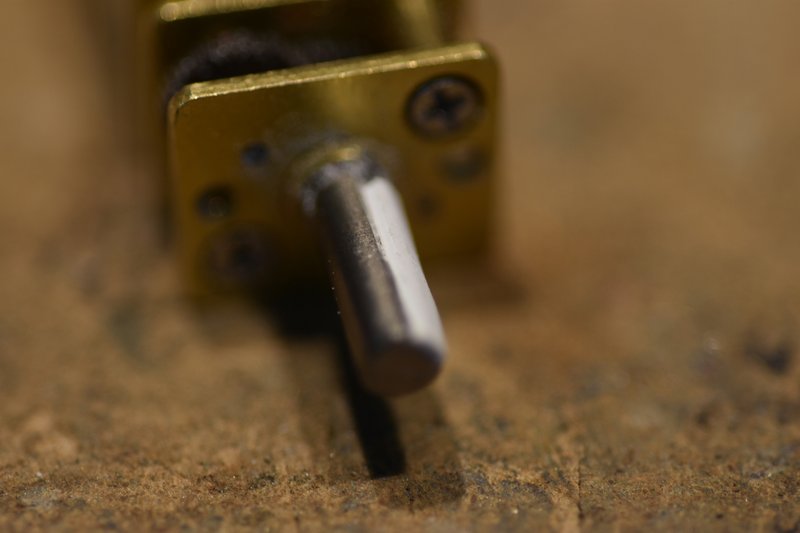 [/img] [/img]After the glue cured I carefully sanded the plastic down until I got a nice snug fit of the hub over the drive shaft. [img] 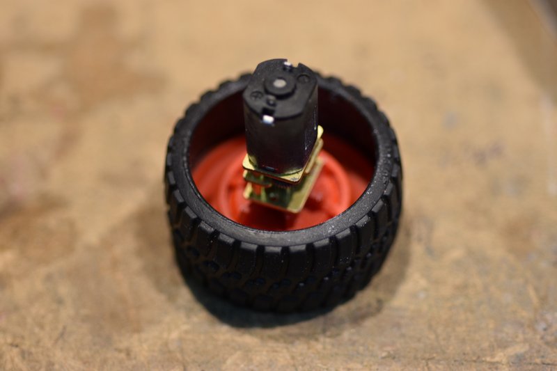 [/img] [/img]Soldered the power wires to the motor and inserted the motor into the support arm. [img] 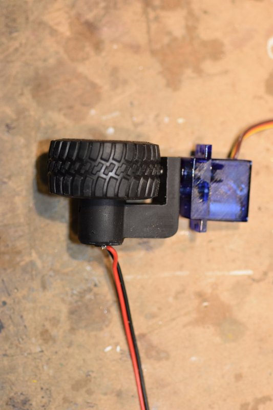 [/img] [/img]On one side of the support arm is a groove. I used this to route the power wires around the back side of the arm. To hold the wires in place I used a few tiny eye screws. These are used to hang pictures and are available in craft stores. [img] 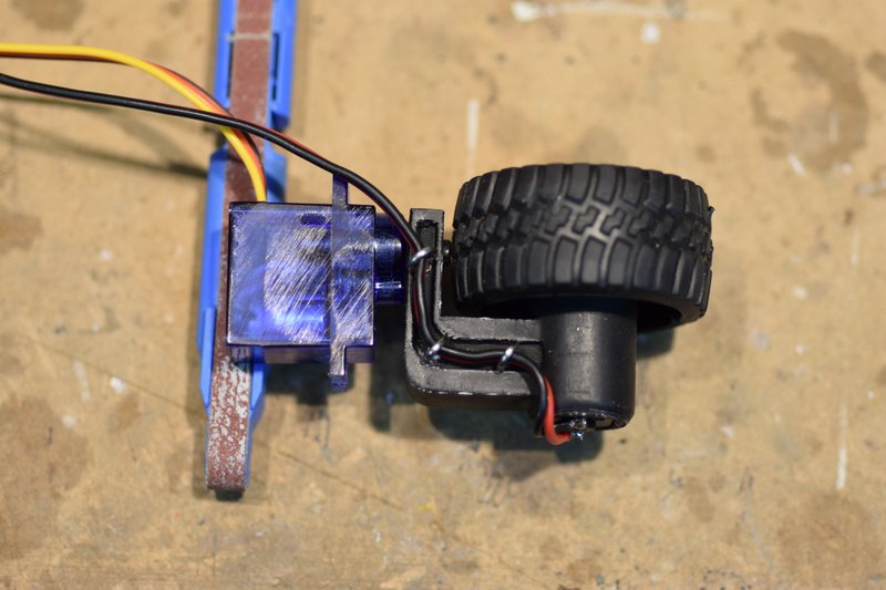 [/img] [/img]I then installed the assembly into the mounting plate installed earlier. The servo has to be inserted from the bottom at an angle and then rotated into final position. I was able to do this as a complete assembly but you could also just insert the servo first and then attach the arm and then insert the motor [img] 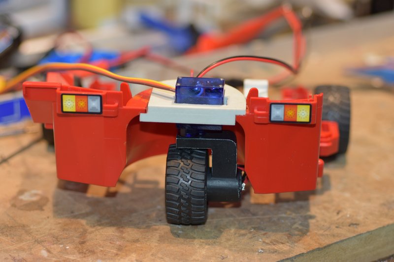 [/img] [/img]Next was to hook it up to a battery and receiver and test the functioning. It worked well but only turned 90 degrees left and right. Well that's the 'normal' range of motion on typical servos. The real world forklifts like this though are capable of ZTR or Zero Turn Radius. That's what I wanted for this model also. The classic fix to get more rotation is to take the servo apart and insert a couple of resistors into it's potentiometer circuit. Yea, that's a pain to do in a standard size servo. I really didn't want to try on a micro servo like this. Fortunately I was using a new Radiomaster TS16S transmitter for this build. It allows me to extend my endpoints out to 150% so I could get more servo rotation without having to modify the servo. It won't get me all the way to a full 180 degrees but it's close enough. [img] 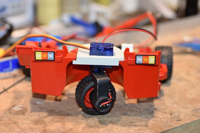 [/img] [/img][img] 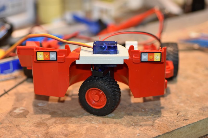 [/img] [/img]That's all for this post. In the next I'll start in on the lift mast. |
|
#11
|
||||
|
||||
|
That looks like it's a really slick and well thought out conversion!
__________________
What do ya mean "Cars are neither Trucks or Construction"? It's still scale, and i play fairly well with others, most of the time... |
|
#12
|
|||
|
|||
|
Yes, the individual who designed these parts did a good job on them. I was really glad to find them.
|
|
#13
|
|||
|
|||
|
Dayum, that came out well. Coupla things I hadn't thought of there, as I blithely assumed the front/fixed wheels would be the driven ones. In your pix, though, I see where there prolly isn't room for even an N20 (maybe a right angle one, maybe) to fit! Fitting one into the steer side is a trick.
Also, dayum on the TX. My beloved Flysky FSi6, even with the tweaked firmware, only goes to +/-120. 'Course I usually use Arduinos for servo stretchers/reversers, but in a conversion like this you just don't have the luxury of that kind of space. And yeah, modifying a 9g is brutal (no way at my age I could even see in there  ) ) One thought on the fork tines drooping. I'd originally designed mine at maybe 100mm, which held fine, but didn't reach across the trailer. I then arbitrarily stretched them out to like 150mm. That let me drop a pallet onto the trailer, but deflected something fierce in doing so. I ended up doing a notch down the length and gluing brass rod in there May or may not be applicable to your setup as mine's 100% 3D printed, and I think a bit bigger (== easier to fiddle with), but since you have the mill you might be able to route a channel down the bottom and fit some reinforcement in. Finally, did the taillights come with the Bruder, and are they stickers or like translucent lenses or something? -- A
__________________
I mean, how hard can it be? |
|
#14
|
|||
|
|||
|
Quote:
|
|
#15
|
|||
|
|||
|
Bruder Piggyback Forklift Build part 4
In this post I'll start on the assembly of the mast lift system, specifically the lift motor and screw. The first step will be to disassemble the mast into it's two main components. There is a looped cable on both sides of the mast and you'll note that each has a clear plastic ball crimped to it and held in a square box on both sides. Using a very narrow screwdriver or similar tool stick the blade into the hole on the back side and carefully pry the balls outward. [img]  [/img] [/img]Then pressing out from the back side the tab shown in the next photo you can pull the upper mast from the lower mast. [img]  [/img] [/img]And we have the two mast assemblies free to work on. It is not necessary to try and separate the lower mast from the base and I wouldn't advise trying. [img]  [/img] [/img]This next photo shows some more of the parts from Thingiverse for this conversion with their associated file names. Most of these parts are for the mast assembly. [img]  [/img] [/img]In my build I did not use any of these parts. I have been building models for decades, long before there were 3D printers. And while I really love my printers I prefer to make some parts out of metal, especially if they will be moving or carrying loads. The thingiverse parts work as attested to by the photos and video the original creator posted on Facebook and If you wish to use them by all means do so. Their assembly will pretty much follow the same procedures I used, you'll just use more glue and fewer screws. As an example, the motor mount from the thingiverse files to me looked kinda thin. Granted, as discussed earlier, you can't lift much weight without tipping the machine over, but the plastic part is glued to the mast and I've had problems in the past with some glues not sticking well to Bruder plastics. This photo shows the printed motor mount on the right and the one I made from a piece of 3/4 x 1/2 x 1/16 in angle aluminum. The screw holes were spaced to match the mounting holes on the lift motor gearbox and a couple of ribs on the mast assembly. [img]  [/img] [/img]I wanted to keep the motor/gearbox as low as possible so that the lift cylinder could be as long as possible. Thus I needed to cut away a portion of the very bottom of the lower mast. The red lines in this photo showed where I cut. [img]  [/img] [/img]And here is the result: [img]  [/img] [/img]The holes for the screws used to attach the motor mount to the lower mast were marked and drilled out. I used #2 sheet metal screws. Note the holes are in line with ribs on the mounting surface to give the screws as much material to bite into as possible. [img]  [/img] [/img]Then a trial fitting of the lift motor.  Note that I used round head screws. This was a mistake. I should have used flat head screws but did not have any at the time and didn't want to go and try to find some. The problem with these round head screws I soon found is that they stick out so far that they interfere with the bottom of the upper mast from being able to slide past. Instead of replacing the screws, what I did was to cut away a bit of the back side of the upper mast until it would clear the screw heads. [img]  [/img] [/img]This is a picture of the lower backside of the upper mast. The yellow dots represent the screw heads for the motor mount. The red lines are where I had to cut away plastic until the upper mast would slide past the screws. While this solution worked, it led to another problem later on. Should have gotten the flat head screws but too late now. Speaking of the bottom of the upper mast, some more surgery is required here as well. Need to cut away a portion of the very bottom so it will slide past the motor/gearbox. Looking down from the top rear, this photo shows with the red line what needs to be cut away. [img]  [/img] [/img]And the upper boom with the piece cut off. This cut also had the benefit of getting rid of the locking tab that prevents the mast sections from being easily pulled apart. [img]  [/img] [/img]Time for the lift screw. The designer of these thingiverse parts used an M3.5 lead screw for his conversion. It came with a plastic nut that he cut down and glued into the 3D printed cylinder. Note from the earlier photo that the cylinder has larger ends to enable the lead screw nut to be inserted in one end and a set screw to be installed in a cross drilled hole to attach the cylinder to the gearbox shaft. Again, I was a little wary of the strength of the cylinder given it's thinness and wasn't sure how long the set screw would stay secure. I decided to go with a brass cylinder assembly. I hunted all over the internet for a source of small diameter lead screws in the US. Absolutely no luck. Finally went to Ali Express. I hate that long wait for the slow boat from China. I needed a lead screw with a brass nut so I could solder it to the brass tube I would use to make the cylinder. I could not find a M3.5 screw with a brass nut so I ended up getting an M4 lead screw that came with a brass nut. The screw I ordered was 150mm long which is plenty for this application. [img] 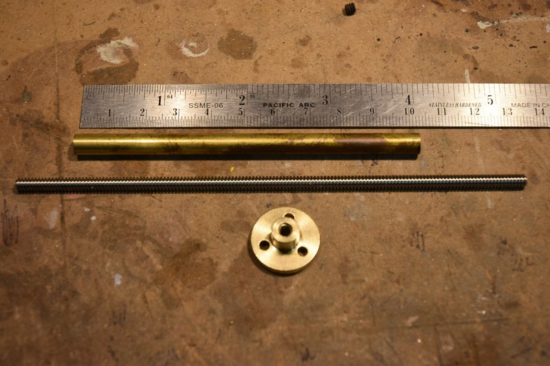 [/img] [/img]Chucked the nut up in a lathe and turned it down to be a slip fit into a 1/4in diameter brass tube. I could have, and found later should have, gone with a smaller diameter tube but I wanted to make sure I could solder the nut in place and keep the solder out of the threads. No tap for these lead screws so would have been a real pain to clean out any solder. [img]  [/img] [/img]I sized the length of the tube by measuring the distance from just above the gearbox mounting screws to the top of the lower mast. I wanted the cylinder to be as long as possible so that I could get the maximum amount of lift without having the screw come completely out the top of the cylinder. Soldered the turned down nut into one end of the brass tube. In the other end I soldered a 1/4in length of brass rod that was then center drilled 3mm to fit the gearbox shaft and cross drilled and tapped for a #6 set screw. Here is a photo of the screw end of the completed cylinder. [img]  [/img] [/img]Next I decided to make a cover to hide the gearbox and motor to make for a cleaner look to the front of the machine. So I designed and printed one up. It is just a snap fit over the motor so can be easily be removed if necessary. [img] 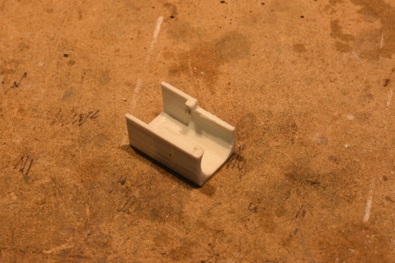 [/img] [/img]Time to check the fit of everything built so far. Attach the motor/gearbox to the front of the lower mast. Attach the lift cylinder to the gearbox shaft. Insert the upper mast onto the lower mast. And, oops, I have a problem. The motor mount is wider that the clearance hole cut in the bottom of the upper mast. No problem. Take everything apart, clamp up the lift motor assembly in a vice and file the sides of the mount down. [img]  [/img] [/img]Put everything back together (get used to doing this) and check fit. Success. This photo shows mast with upper section raised. [img]  [/img] [/img]And with the upper mast section fully lowered. [img]  [/img] [/img]That's all for this post. In the next I'll show what is probably the trickiest part of this entire project. Assembling and adjusting the limit switches. |
|
#16
|
|||
|
|||
|
Quote:
And M3.5? Who thought of that? Sheesh. I bow to your successful use of the N20's. I've only recently looked at them as I've previously used the 9gs, but the gearing coupled with the even smaller size is attractive. Wrt lighting, one word: Arduino. Yes, you gotta learn a bit of "programming", but there are a bazillion tutorials on the web so it's not a word to be afraid of. Also, they are just MADE for this sort of thing; they drive LED's almost directly (fine, you need a resistor), and can come in fairly tiny form factors. I don't know your TX setup well, but mine sends out all of its channels on essentially an RS232 serial bus, ie like those on a computer, so it's easy to make work with the Arduino. Then you just read the channels, and say something like if (channel[1] < 1450) {turnonLED(left);} // left turn else if (channel[1] > 1550) {turnonLED(right);} // right turn else {turnoffLED(left); turnoffLED(right);} total psuedocode, not exactly how it's written, but you get the idea. The deadband of 1450...1550 in the middle lets the stick float a little before doing the lights. If your stick is hyperaccurate you can turn it down to 1495...1505 or whatever (see below about making changes via pushing buttons!  ) )If instead it's auxiliary lights on a switch, you just do if (channel[6] > 1750) {turnonLED(aux);} // switch on else {turnoffLED(aux);} // switch off Blinking is a bit more complicated, but you start simple and work your way up. The key thing in my mind is that once you get the 'dweeno and the LED's set up, the rest is done in software, so if you want to add new features or blink patterns or whatever, you don't have to swap out the board, just USB it to your computer and upload the new code. I tend to use these guys https://www.arduino.cc/en/pmwiki.php...noBoardProMini They're about 0.7" x 1.3" (err, 18x33mm), and the generic ones are a coupla bucks per, especially if you get a multipack. They'll run right off a 2S LiPo, or the RX BEC if you're using 3S+. They can drive servos directly, easy peasy, and like I said LED's just need one resistor, so the basic RC stuff is a breeze. There are smaller boards if you're that tight for space, but you tend to lose functionality as they don't have room for connections for the fun stuff. Anyway, I'll stop proselytizing now =)) but feel free to inquire if you're interested. (Also I think some of my build threads have more detail as they use one or multiple Arduinos.) -- A
__________________
I mean, how hard can it be? Last edited by dremu; 09-03-2021 at 08:34 PM. |
|
#17
|
|||
|
|||
|
Actually I have played around with Arduinos and Raspberry Pis since the Arduino Duemilanove board came out. I just don't think that there is room inside the lift for even a nano sized board. The nano has a 30mA limit per pin so even with just 2 LEDs on a circuit you might need to also incorporate a switching transistor besides the resistors. I used a RasPi Zero as the basis for my portable message sign that I built a couple of years ago. I recently acquired some arduino nano clones that have packet radio capability that I am going to try to integrate into another project that I'll post up if it works out. I would really love to see some one do one of these piggyback conversions and be able to incorporate lighting, just not going to be me at this time.
|
|
#18
|
|||
|
|||
|
Bruder Piggyback Forklift Build part 5
I'll start this posting off by installing the lead screw. In the previous post there was a photo showing 5 of the parts that can be used for this conversion from Thingiverse. The originator of these parts did not incorporate any way to secure the lead screw to the mounting piece that goes on top of the upper mast assembly. Looking at the photos of his build he posted on Facebook he simply just glued the lead screw to the top of the mount with a blob of some kind of adhesive. This is the one thing about his build that I really did not like. I decided to make my lead screw mount out of 1/4" aluminum bar stock. Photo shows the top of the upper mast, the 3D printed part from thingiverse and the aluminum bar stock I used to make my mount. I used my milling machine to make this part but I've made similar parts in the past with a fine tooth hacksaw, files and a little patience. I used the same dimensions as the 3D printed part except I did not add the boss in the top center. What I added was to cross drill through the center hole and tap for two set screws, one from each side. These would hold the lead screw in position and keep it from turning. [img] 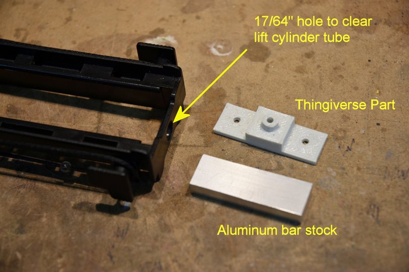 [/img] [/img]The hole you see in the top of the mast was sized to allow the 1/4" tubing being used for the lift cylinder to extend through to the bottom of the lead screw mount. The hole was located using the 3D printed part as a guide by holding it in position on the top of the mast and sliding a transfer punch through the center hole. This photo shows the lead screw mount secured in place at the top of the upper mast. [img] 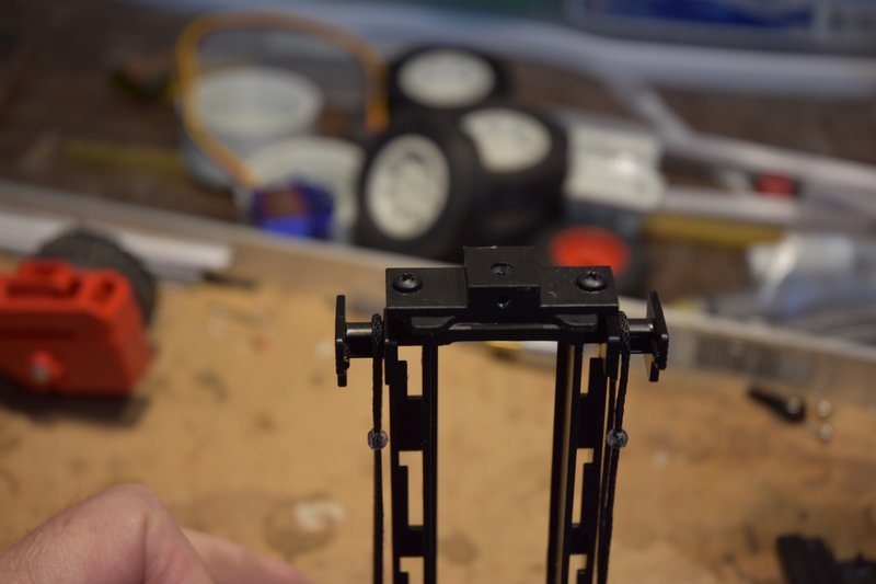 [/img] [/img]Next is to determine the length of lead screw needed. To do this I put the upper mast back on the lower mast and placed the assembly back on the lower body. I blocked up the rear of the body to match the height of the original toy and set the forks to the same level. [img] 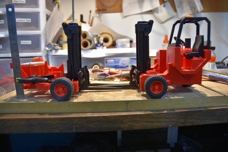 [/img] [/img]Then I ran the lead screw down through the top of the mount, down though the cylinder until if hit the top of the gear box shaft at the bottom of the cylinder. Unscrewed back about 1/2 turn and marked the lead screw at the top of the mount. This is where the excess screw needed to be cut off. [img] 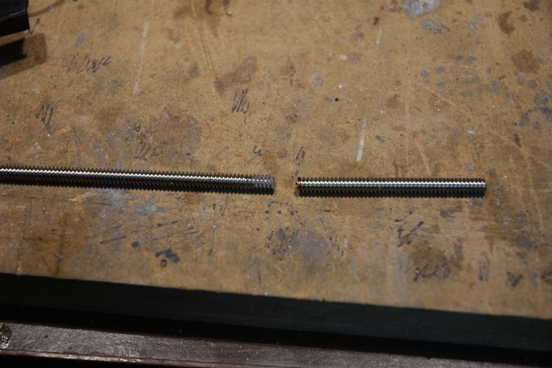 [/img] [/img]After cutting the excess off I filed two flats on the end of the screw for the set screws in the top mount to bear against and keep the lead screw from turning. BTW: one big benefit of having my parts assembled with screws as opposed to gluing them, it is relatively easy to remove the lift motor, cylinder and lead screw to check fits and make adjustments. I bet I had these parts in and out a couple of dozen times during the conversion. Next comes the real fun, the limit switches. The fourth photo of my last post shows some of the parts in the Thingiverse files. We need the part in the lower right called 'ups_tipper'. This part actually serves two purposes. The back side will hold the servo for tipping the mast forward and backwards. The front side serves as the mounting plate for the limit switches. Start by cutting some plastic away at the top of the bottom mast section. The red dashed lines in the photo below show where to cut. [img] 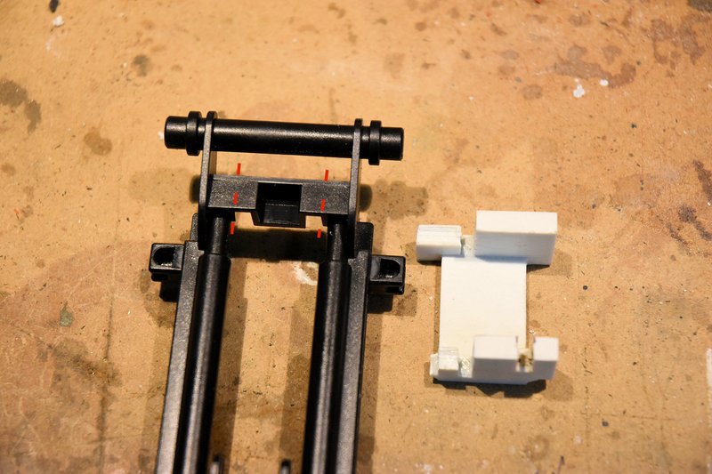 [/img] [/img]And here is the lower mast with the plastic cut out. [img] 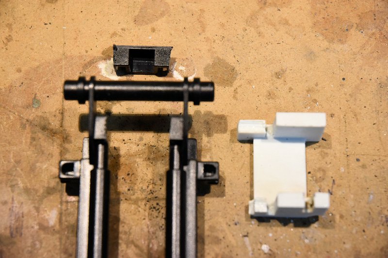 [/img] [/img]The printed part fits in as shown. The curved portions of the part should fit on the curved sections of the mast which I guess are supposed to represent hydraulic cylinders. [img] 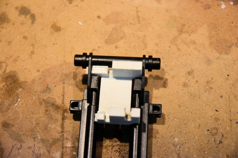 [/img] [/img]This is what the front of the lower mast looks like with the printed part in place. [img] 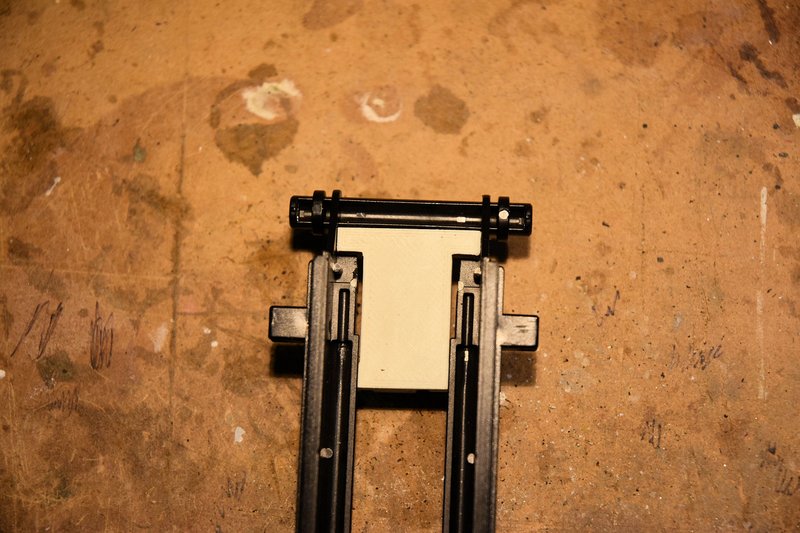 [/img] [/img]Fortunately for me I did not glue this part in place. I thought it might be a good idea to check the fit of the switches I was going to use and make sure they would fit between the mounting plate and the lift cylinder. They did not!!! I was using the same size/type switches that the originator of the parts files used. These are 2A mini snap switches and are about 5.8mm thick. After some head scratching the cause of the problem was obvious. The printed cylinder is much smaller in diameter than the 1/4" brass tubing I used to make my cylinder. If you use the printed cylinder and other parts and the same type of switch you probably won't have this problem, but check the fit before gluing anything in place. How to fix. I wasn't going to scrap the brass cylinder. What I decided to do was redesign and print a new mounting plate. After a lot of careful measuring I determined I needed about 2mm more clearance between the mounting plate and the backside of the cylinder. I basically copied the original part but extended the mounting posts by 2mm. I also added a notch to the servo side to clear the servo wires as the micro servo I was going to use had it's cable exiting the body about half way down it's length instead of at the bottom like the mount was designed for. I next found another problem. By moving the switches back 2mm their arms would no longer hit the parts of the upper mast assembly they needed to hit in order to operate. The fix for the top switch (which stops the lift motor as it lowers the mast) was to simply glue on a piece of styrene at the top back of the upper mast extending the contact point back to where it will hit the switch arm. It was left taller than needed and will be filed down to tune the stopping point later. [img] 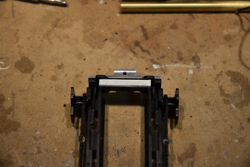 [/img] [/img]The fix for the bottom switch (which stops the lift motor as it raises the mast) was a bit more complicated. First I glued in a square piece of styrene that went across the inside of the left upper mast frame. It sits right on top of the part I had to cut plastic from to clear the round head screws I used to mount the lift motor. NOTE: even if you use the 3D printed parts, if you use round head screws for mounting the motor you may have to do this same procedure for the lower switch. I also had to file away some the plastic I added at the front to clear the fork mount. [img] 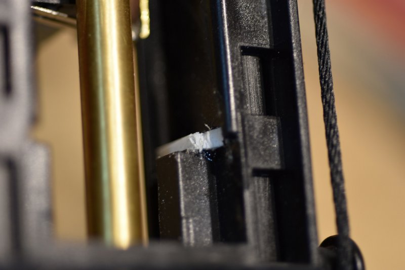 [/img] [/img]I then had to modify the arm on the switch as it's position would be too low to hit the plastic trip bar I just added. I cut and shaped an extension to solder onto the end of the switch arm. And truthfully I just eyeballed it's length and shape knowing that I would have to reshape and adjust it's position when fine tuning. Finally, just to make sure the switches would fit I sanded both sides of each switch to make them just a little thinner. Have to be careful that you don't take too much off or the latches that hold the switches together will fail. This photo shows both switches prior to being installed. [img] 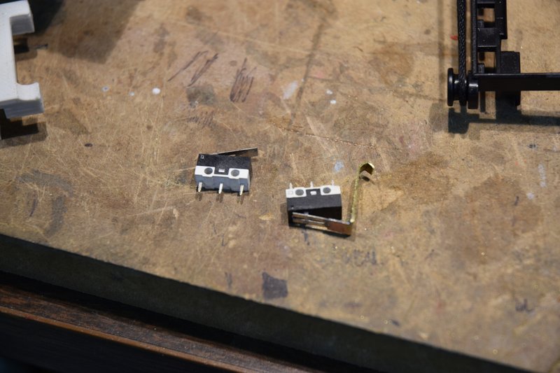 [/img] [/img]
|
|
#19
|
|||
|
|||
|
Bruder Piggyback Forklift Build part 5b
(Had to split this post because of posting size limitations) I glued both switches to the mounting plate in positions shown. The switch on the left will be on the bottom when installed in the mast. When cured I soldered diodes and a jumper wire in place. I used 1N4003 diodes which are rated for 1A which is plenty for these little N20 motors. Then tested the switches to make sure the circuit worked properly. [img] 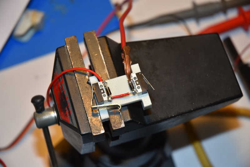 [/img] [/img]At this point I was now ready to glue the switch mounting plate into position at the top of the lower mast. I used a 2 part epoxy for this. While the epoxy was curing I wired up the lift motor with extra long leads that could be trimmed as needed later. The red wire will go up to the limit switches and the black will go to the motor ESC in the body of the lift. [img]  [/img] [/img]Next was to run a longer than needed wire into the bottom backside of the lower mast and run it up the right side of the mast to the switches. The lift motor was reinstalled and it's red wire was also run up the right side to the switches. I cut a small notch in the side of the mast even with both switch's lugs and bent one wire over to each switch and soldered into place as shown. [img] 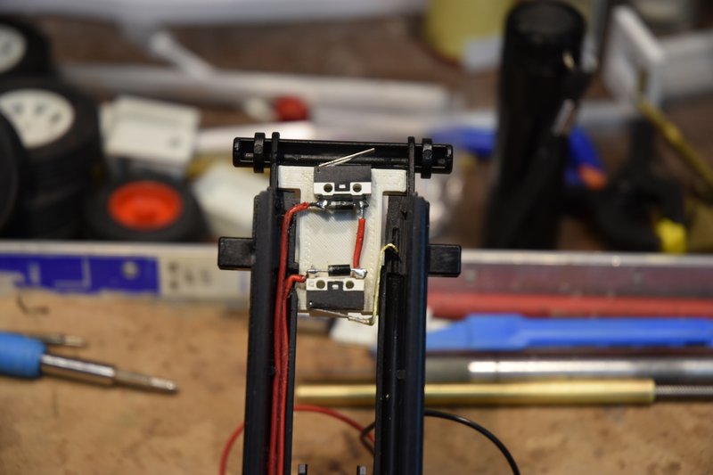 [/img] [/img]This photo shows the lower mast assembly with the lift motor and completed limit switch mount and wiring in place. Big sigh of relief. [img] 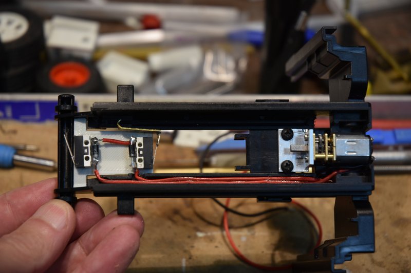 [/img] [/img]The only thing left was to fine tune the activation of the limit switches. Put the upper mast assembly back into position in the lower mast and installed the lift cylinder. Connected a temporary power supply to the wires from the lift motor and started running the mast up and down. Adjusting the top switch was fairly easy. After lowering the mast till it came to a stop, check the position and if was still a little high just sand a little bit more off the bottom of the trip plate on the top of the upper mast. It ended up looking like this. [img] 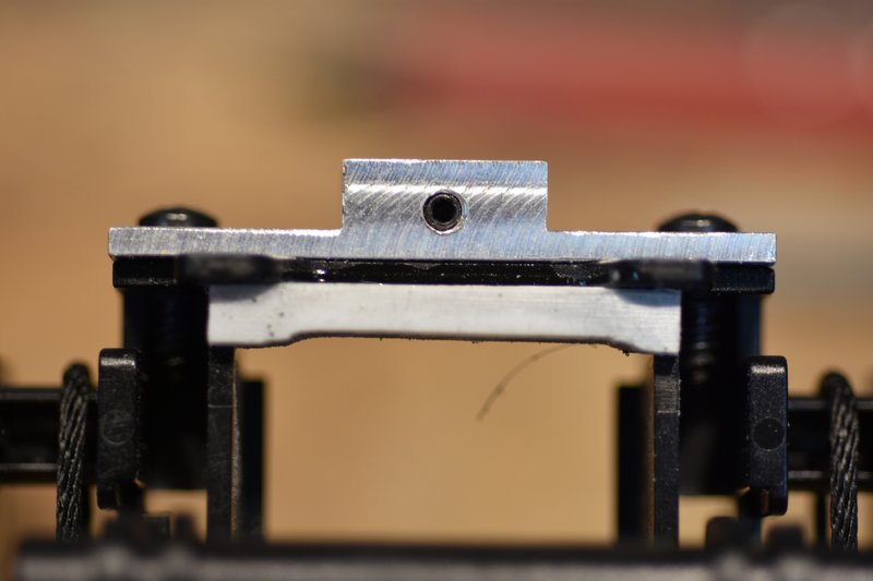 [/img] [/img]Adjusting the action of the lower switch was a bit trickier. I started with the end of the extension I added to the switch arm bent a bit lower than where I knew it needed to be. Raise the upper mast and see where it would stop. Then carefully reach in with a set of needle nose pliers and/or needle file and carefully make a small adjustment to the bend or length of the hook and try again. Took some time but eventually got there. Really big sigh of relief. [img] 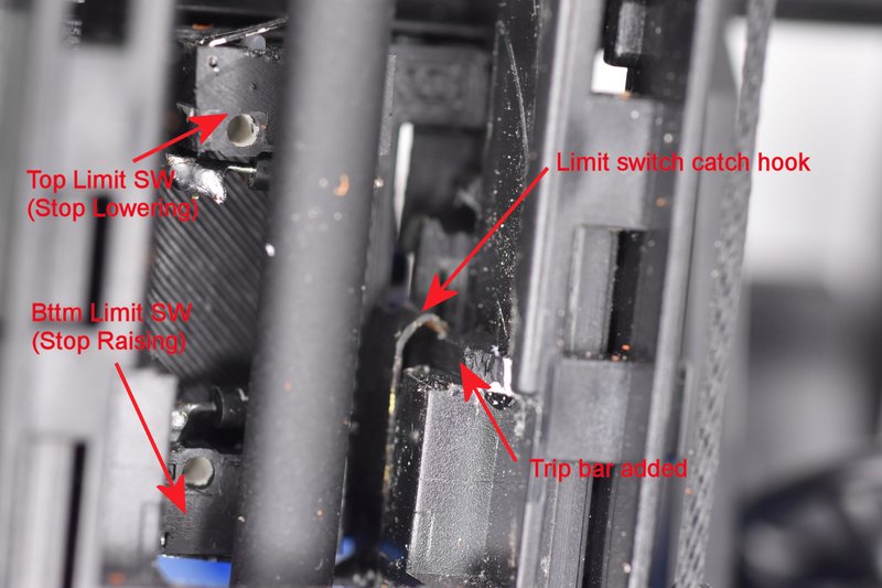 [/img] [/img]I will admit to another error I made. If you look closely at the last photo and the one showing the limit switches mounted at the top of the mast above you might notice that the polarity band on the diodes have changed position. Apparently because I used two red wires up the mast to the switches I didn't pay enough attention to which was which and I got them backwards. The wire to the lower switch was now too short to reach the upper switch so I couldn't just swap them so I had to swap the diodes end for end. Since they were already mounted that meant the swap had to be done with them inside the mast. Not much room for error with a hot soldering iron. Pay attention! Here is a photo of the completed mast lift assembly from the front; [img]  [/img] [/img]and the back. [img] 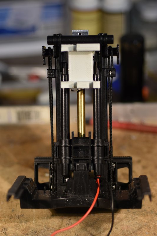 [/img] [/img]That's all for now. In the next part I'll show how the mast tilt assembly goes together. |
|
#20
|
|||
|
|||
|
Quote:
Wrt the current limit, though, I just drive one LED per pin, and haven't had any trouble at 20mA. Cuts down on component count, but as you say, room is still at a premium. I know Adafruit has their Trinket line that are tiny, or maybe you could just use a bare '328 chip, but then you need a voltage regulator and at least a connection to program it ... ugh. Anyway, I'll stop going off topic, and just say wow. I'm particularly interested in the limit switches as I wanna do something similar for a telescoping column for another project and I have a box of those very switches awaiting the time and work. -- A
__________________
I mean, how hard can it be? |
 |
| Currently Active Users Viewing This Thread: 1 (0 members and 1 guests) | |
|
|