![]() |
|
Electronics tech Anything to do with the electronics in a model. Lights, Radio, ESC, Servo, Basic electrical. |
![]() |
|
Thread Tools | Display Modes |
#21
|
|||
|
|||
![]()
The way I see it I have the following circuits for the tractor..
Two bulbs for fog lights, Two bulbs for low beams, Two bulbs for high beams, 7 bulbs for marker lights, one front left turn signal, one front right turn signal, 3 back up lights, 2 rear combination brake and turn signal lights. So that is a total of nine circuits.
__________________
Dean Cory Knox, IN |
#22
|
||||
|
||||
![]()
The light is cabled like this:
Battery + -> resistor -> led + (long pin) Led - (short pin) -> output pin at the USM-RC-2 You can also put the resistor behind the LED. For 7.4V circuits I use 220Ohm resistors.
__________________
Greetinx Peter To view links or images in signatures your post count must be 10 or greater. You currently have 0 posts. |
#23
|
|||
|
|||
![]()
I run 3S lipo Packs (I use them in my crawlers, Quad Copters, Airplanes and RC Cars.
That would give 11.2 volts fully charged and cut off at 9.6 volts. What resistor would you suggest?
__________________
Dean Cory Knox, IN |
#24
|
|||
|
|||
![]()
Well this calculation was wrong. Not correct for my exact bulbs
__________________
Dean Cory Knox, IN Last edited by DrDiff; 12-17-2017 at 01:51 PM. |
#25
|
||||
|
||||
![]()
Hi,
the needed resistor can be calculated. Ser this page. LED resistor calculator Just ensure that your LEDs are mounted parallel, not in a row.
__________________
Greetinx Peter To view links or images in signatures your post count must be 10 or greater. You currently have 0 posts. |
#26
|
|||
|
|||
![]()
OK now that I know how to get the proper resistance value,
Do you have a suggestion where I can get them? Quote:
__________________
Dean Cory Knox, IN |
#27
|
||||
|
||||
![]()
Any reason you're tapping power for the LEDs at pack voltage instead of going through the bec and tapping recciever voltage?
If you like local, see if you've got a Radioshack still around, or an electronic surplus place. Ebay can get you a lifetime supply of them for like $2. Mouser, digikey... Just plug your ohm value into a search engine.
__________________
What do ya mean "Cars are neither Trucks or Construction"? It's still scale, and i play fairly well with others, most of the time... |
#28
|
|||
|
|||
![]()
This is the sound module that controls the lights and sounds.
![]() Negative is pulled off the rainbow cable into the resistor through the LED and back into the left hand side of the sound module. It operates off of pack voltage and not the 5 volt off of the rx.
__________________
Dean Cory Knox, IN |
#29
|
|||
|
|||
![]()
Did the first test with the Taranis Plus. I am confused although the signal for the steering servo goes through, I can not figure out how to program the turn signals to flash and the blinker noise to go off when the steering servo moves.
__________________
Dean Cory Knox, IN |
#30
|
|||
|
|||
![]()
OK So, I have the Sound Teacher software open and am on the Configuration tab, on the proportional sounds tab. /i am in mixed mode. I want my turn indicators or blinkers to work with the steering channel, CH1 out of the RX. But there is not a tab labeled Prop#1
So my question is on hook up of the steering servo so that I can tell the turn indicators to function with the steering servo?
__________________
Dean Cory Knox, IN |
#31
|
||||
|
||||
![]()
Hi,
by default the Sound Teacher doesn't have a "tickbox" to activate the indicators if the steering is moved. But there's a possibility to do that. First you must connect the steering channel with the USM. If your steering is on Channel1 on your RX, you connect the Channel 1 with the upper Prop#2 connector at the USM. Now you plug the steering servo into the lower Prop#2 connector. Both connectors are connected, so the USM is listening to the signal that is going to the servo. Now you step into the configuration of the proportional channels. We must edit Prop#2 ![]() First you must change the settings of the areas. Please make the area B and C smaller and the A and D bigger. Now you configure the indicators as static functions on the areas A and D. The areas B and C define the steering area the indicator doesn't start. So you can correct the riding without starting the indicato directly on every tick to the channel. As soon as the steering enters area A or D, the indicator starts and as soon as the area is left again, it stops again. If the indicator starts too early, increase the areas B and C again a bit. I hope this helps you to implement your wishes and requests.
__________________
Greetinx Peter To view links or images in signatures your post count must be 10 or greater. You currently have 0 posts. |
#32
|
||||
|
||||
![]()
Hi Dean,
here you can activate the digital mode: ![]()
__________________
Greetinx Peter To view links or images in signatures your post count must be 10 or greater. You currently have 0 posts. |
#33
|
||||
|
||||
![]()
Hi,
another hint to your indicators. as shown above you can activate the indocators by moving the steering. I'm using this in combination with an alternative configuration. I'm using the EKMFA to activate the wanted functions. ![]() In addition I configure the indicator to be switched off via the steering ![]() Now I do have 2 possible ways touse the indicator. 1. I can activate the indicator a time before I make the turn by using the EKMFA. It will be automatically turned off if I steer back. 2. I let the Prop#2 settings activate and deactivate the indicator Both options can be configured together, they do not exclude each other.
__________________
Greetinx Peter To view links or images in signatures your post count must be 10 or greater. You currently have 0 posts. |
#34
|
|||
|
|||
![]()
Just got my beier and started programming sound for my 870k and then I'll setup led lights. I'm also usingb3s Lipo and had the same question. Fully charged 3s Lipo has 12.6v so which resistor did you use? The manual shows which one to use for nimh 12v batteries.
|
#35
|
||||
|
||||
![]()
Hi...
just use an LED resistor calculator, enter the values of the LEDand you'll get the needed resistor value.
__________________
Greetinx Peter To view links or images in signatures your post count must be 10 or greater. You currently have 0 posts. |
#36
|
|||
|
|||
![]()
ifmys10: I bought my LEDs here... lighthouseleds.com. Since I have 3S Lipo batteries I used 12 volt pre wired LEDs.
For example the high beam headlights, I soldered the black wires (negative from the LED) on both sides together and then connected it to the appropriate wire from the rainbow harness. the red wires from the LED's are soldered together and then a jumper wire takes that to #8 on the left side of the soundmodule [the side where the power comes into the unit] Quote:
__________________
Dean Cory Knox, IN Last edited by DrDiff; 01-30-2018 at 09:23 PM. |
#37
|
|||
|
|||
![]()
I started to connect the black wires from the LEDs to the oundmodule. I had intended to use the optional plug in rainbow wire harness. However the more I tried to use it, the more problems I had.
So I went back to the original rainbow harness and started soldering the lights to the individual wires. I still have to connect the front and rear Fog Lights, the tail lights, back up lights, and the front and rear turn signals. As soon as I get my tax refund I am going to order the UFR-1230 ESC Pictures soon!
__________________
Dean Cory Knox, IN Last edited by DrDiff; 01-30-2018 at 09:32 PM. |
#38
|
|||
|
|||
![]()
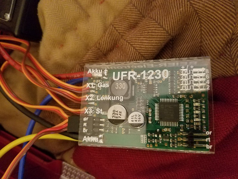
I got my Beier UFER 1230 ESC today. Steering and throttle work fine. Sound and lighting effects have all gone out the toilet!
![]() ![]()
__________________
Dean Cory Knox, IN Last edited by DrDiff; 02-14-2018 at 05:16 PM. |
#39
|
|||
|
|||
![]()
Any updates on this? Alot of good info in here.
|
#40
|
|||
|
|||
![]()
Great information with the pictures.
|
![]() |
Currently Active Users Viewing This Thread: 1 (0 members and 1 guests) | |
Thread Tools | |
Display Modes | |
|
|