|
|||||||
| Construction Equipment If it digs, pushes, hauls dirt "off road" post it here. |
 |
|
|
Thread Tools | Display Modes |
|
#41
 12-28-2020, 04:50 PM
|
|||
|
|||
|
opps !
After several trial configurations i have settled on this:  i found the bevel gears wanted to push each other apart under load so i had to move the larger gear up against the chassis to get rid of any deflection. I also had to fab a motor mount for the two 24v dc motors: the ABS 3d printed one just was not strong enough for all the torque  Image shows the steel bar that connects the two undercarriages together: 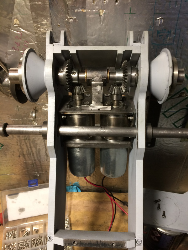 it has a thread and counter sunk bolt at each end to pull it all together and then a couple aesthetic covers to hide them.    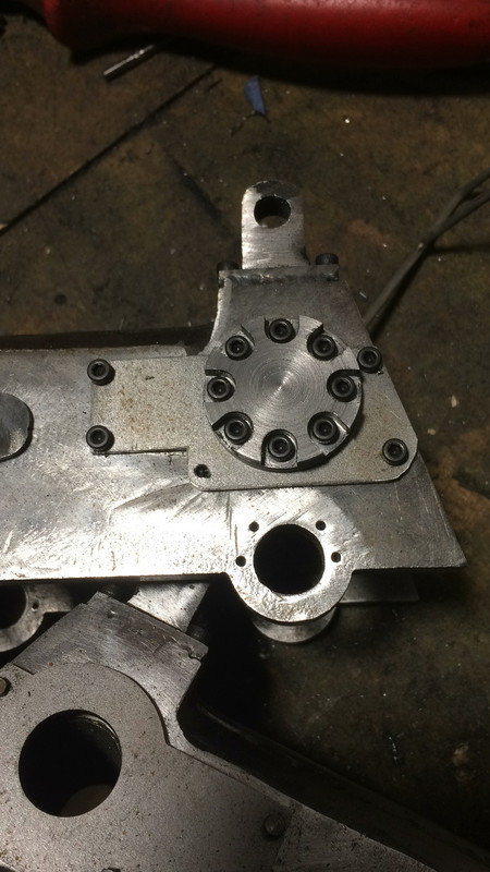 I am still amazed by how much time all these little things take to make ! 
|
|
#42
12-28-2020, 05:06 PM
|
|||
|
|||
|
For a bit of a break from all the hand cranking operations on the mill and lathe i also started on 3D printing the cab and top elements that had no structural importance and were just for show.
  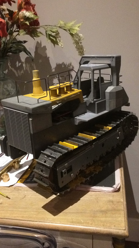 the railings are just 2mm steel rod and bend/silver soldered together. really happy how these worked out! my original idea was to weld all the elements of the undercarriage together ( bolted together first) and then two pack fill and sand/undercoat: 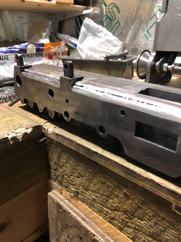   Filled and primed :  Yellow colour is just a filler/primer for the ABS prints and is used an acid etched primer for the steelwork  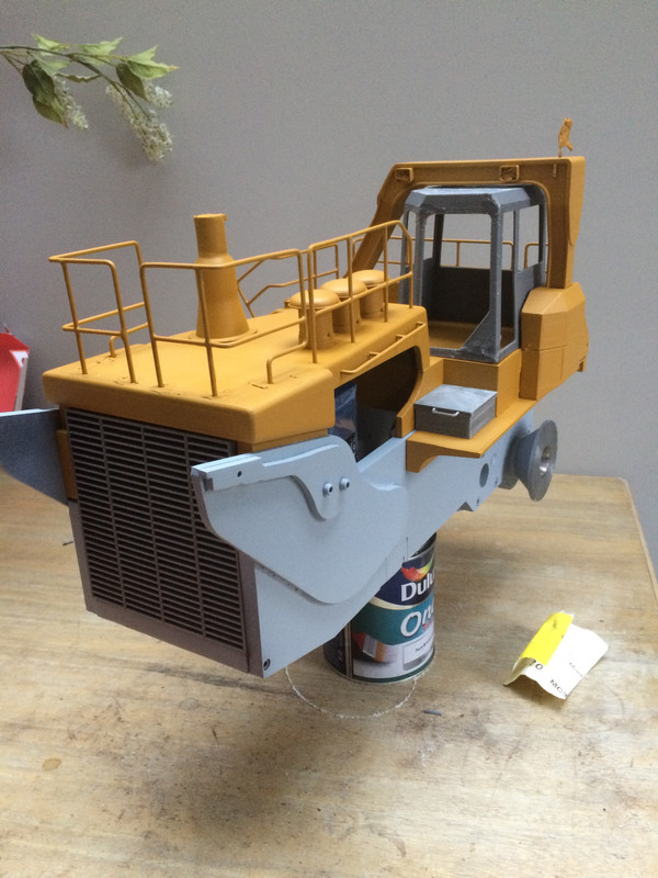    
|
|
#43
12-28-2020, 05:53 PM
|
|||
|
|||
|
Which brings us back to electronics !
So i did have this running ( up off the tracks on a stand) using a 2x32a Sabertooth controller from my openTX transmitter ( Radiomaster 16 channel) and it ran as expected (very well). The only problem was when i was at full stick forward the RPM of the track was about 30RPM at the sprocket. Far to fast for what i wanted. With the sabertooth, you can just ease off the stick to slow down but that comes at the cost of torque as the controller just turns down the voltage, slowing the motors. A 24v motor running at 9 v just isnt as strong at one at full power. Thought about gearing the motors down further ( way to much work and i really didn't want to go back to the drawing board on the transmission!) but i remembered another build thread that talked about PWM control of DC motors. Main benefit being that you just pulse the motors very fast for a percentage of time so that the motors slow but are still getting 24v ( but only for very rapid short bursts) So after a few weeks i ditched the sabertooth in favour of the following PWM setup: 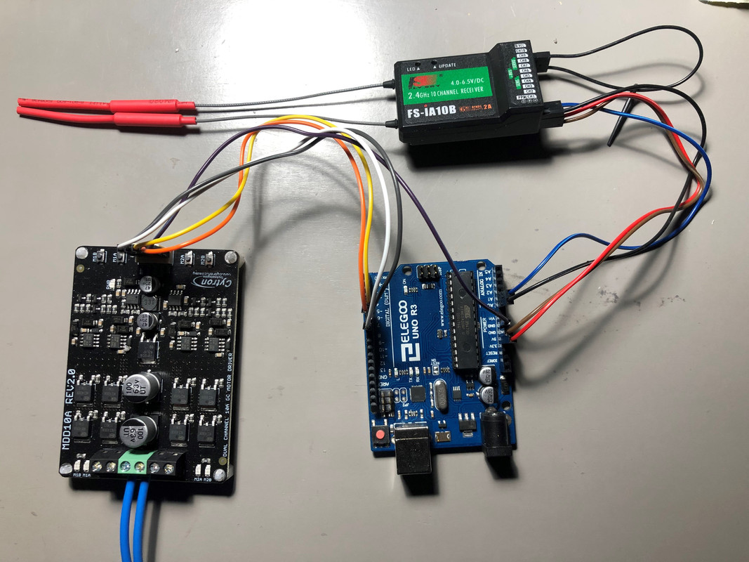 OpenTX radio talks to two channels on the receiver. 2 channels on the receiver are connected to inputs onto an Arduino microprocessor Outputs from the Arduino are PWM signals for motor speed and another for motor direction which get connected to a PWM capable motor driver. That's the easy part ! The hard part was writing the code for the Arduino. After a couple weeks of Arduino code for dummies and watching every youtube tutorial possible i was able to write the code for differiantial/tank steering. its a steep learning curve but well worth the effort. Its not just the benefits of PWM motor control but also being able to control lighting, sound or anything really you wanted. I will post the code below so that hopefully it may help someone else one day. Setup: Open TX TX16s transmitter (2 channels for drive motors) 10ch receiver Arduino Uno (Elegoo starter kit) Cytron MDD10A Dual Motor Driver (PWM input) 2x24v brushed DC motors with 1:72 planetary gearboxes 7s LiPo at 24 v Code: int dir1 = 7; int dir2 = 4; //the following are all ~PWM capable ports int pwm1 = 6; int rc_channel4 = A0; int pwm2 = 5; int rc_channel2 = A1; void setup() { TCCR0B = TCCR0B & B11111000 | B00000010; // for PWM frequency of 7812.50 Hz (Output pins 5,6) pinMode(rc_channel4, INPUT); pinMode(dir1, OUTPUT); pinMode(pwm1, OUTPUT); pinMode(rc_channel2, INPUT); pinMode(dir2, OUTPUT); pinMode(pwm2, OUTPUT); Serial.begin(9600); } void loop() { int pwmA = 0; int rc4 = pulseIn(rc_channel4, HIGH, 35000); int pwmB = 0; int rc2 = pulseIn(rc_channel2, HIGH, 35000); Serial.print(" raw channel4: "); Serial.print(rc4); Serial.print(" raw channel2: "); Serial.print(rc2); delay(100); if (rc4<1450 && rc4>1400) { Serial.println(" stick centered"); analogWrite(pwm1, 0); } if (rc2<1450 && rc2>1400) { Serial.println(" stick centered"); analogWrite(pwm2, 0); } if(rc4 > 1450){ //right stick pwmA = map(rc4, 1450, 1910, 0, 255); //map our speed to 0-255 range digitalWrite(dir1, LOW); analogWrite(pwm1, pwmA); pwmA = constrain(pwmA,0,255); Serial.print(" right stick speed: "); Serial.println(pwmA); } if(rc2 > 1450){ //left stick pwmB = map(rc2, 1450, 1910, 0, 255); //map our speed to 0-255 range digitalWrite(dir2, HIGH); analogWrite(pwm2, pwmB); pwmB = constrain(pwmB,0,255); Serial.print(" left stick speed: "); Serial.println(pwmB); } if(rc4 < 1400){ pwmA = map(rc4, 1400, 920, 0, 255); //map our speed to 0-255 range digitalWrite(dir1, HIGH); analogWrite(pwm1, pwmA); pwmA = constrain(pwmA,0,255); Serial.print(" right stick speed: "); Serial.println(pwmA); } if(rc2 < 1400){ pwmB = map(rc2, 1400, 920, 0, 255); //map our speed to 0-255 range digitalWrite(dir2, LOW); analogWrite(pwm2, pwmB); pwmB = constrain(pwmB,0,255); Serial.print(" left stick speed: "); Serial.println(pwmB); } delay(10); } I raised the frequency of the PWM to remove the high pitch whine and increase driver efficiency but not necessary. I have this working on my desktop (image) and its working as i would want. once its installed i may have to tweak the steering inputs but generally its a good starting point. Thats enough for one day ! feel free to ask questions if needed Rob
|
|
#44
12-28-2020, 06:33 PM
|
|||
|
|||
|
Great work, was really nice to get an update. I really like the idea of using the Arduino and thanks for sharing the code. What will the approximate size of your machine be when finished?
|
|
#45
12-29-2020, 05:35 AM
|
|||
|
|||
|
Hi Zabco
the total length will be about 850 mm and the blade is 460mm wide (think its a coal blade). depending on a test on how it pushes dirt I may have to opt for a smaller blade width. ill see how it goes as with most of this, its trial and lots of errors  I threw all the metal for the blade and ripper on scale with the chassis and its already at 55kg ! its hard enough moving it about already ! can recommend the Arduino enough but If you use the code you will have to tweak the input ranges for your specific RC transmitter/ deadbands. I am sure they all vary a little bit. Rob
|
|
#46
12-29-2020, 08:50 AM
|
||||
|
||||
|
Congrats on a nice build and thanks for sharing your experience as a first time coder
__________________
Emil G | MFZ Blocher Fendt 926 | RC4WD Volvo EC480 excavator | Carson LR 634 | Kenworth 6x6 hauler | Kenworth 6x6 dtrk My channel: To view links or images in signatures your post count must be 10 or greater. You currently have 0 posts. Construction site on Facebook: To view links or images in signatures your post count must be 10 or greater. You currently have 0 posts. Pictures on Instagram: To view links or images in signatures your post count must be 10 or greater. You currently have 0 posts.
|
|
#47
12-29-2020, 11:57 AM
|
||||
|
||||
|
Great looking machine!
I've got to say, coding your own dual esc is really impressive! i would have totally wimped out and just run 2 seperate esc and setup a channel mix through the radio
__________________
What do ya mean "Cars are neither Trucks or Construction"? It's still scale, and i play fairly well with others, most of the time...
|
|
#48
12-29-2020, 05:51 PM
|
||||
|
||||
|
Very Nice work Rob.
That coding definitely sounds complicated to me. You may have to build planetary reductions in your final drives to slow her down thus having full power to the motors. That would take a lot of the stress off of your bevel gearing that you said you're already having trouble with. I'm not up to date on all of the RC electronics but; Don't the brushless motor speed controllers act like an AC Inverter? I have some of my machinery and mills in my shop equipped with 208VAC 3phase inverters to control the motor RPM. It seems I get full torque using them at low speeds. I get a chance, I have a picture I'll post taken 29yrs ago of the first D575A built with my son and I standing next to it.
|
|
#49
12-29-2020, 06:36 PM
|
|||
|
|||
|
Quote:
|
|
#50
12-29-2020, 07:01 PM
|
|||
|
|||
|
Hi !
Really appreciate the kind comments Ideally I would to have liked to rotate each motor 90 degrees so that the motor shaft connected straight onto the sprocket but the space inside didn’t really allow it, well not for the motor/gearbox I chose. That would get rid of the need for a right angle transfer. When I first started at this I couldn’t really find any information on how much torque is required to make a 100lb model move itself and then somehow still have enough power to push a blade full of dirt so I just opted to get the highest torque motors that I could fit inside the frame. There are a few D10 builds on the forum that have used wiper motors out of cars etc but none really mention the motor specs In terms of rated torque. The ones I have chosen do have planetary gears already and are rated at 10nm continuous and can do shorter periods of up to 25 mm. Is it enough ? I don’t really know ! But I will post some results when it’s all put together so that the next person may benefit from all this. I’m not really knowledgeable about inverters etc to comment but from a crude physical test ( hands holding sprocket) between the sabertooth @20% stick and then the PWM setup at 20%, I couldn’t slow the PWM at all , whilst the sabertooth I could make the motors slow/labour. Again I’m not expert at all and it’s just trial and error. Please post the picture, I would be really interested in seeing it !! Rob
|
|
#51
01-02-2021, 11:42 AM
|
|||
|
|||
|
Hi everyone !
First test video..... actually the first test at my mates allotment went ok until the set screws holding the gears to the axle gave up the ghost after 10 mins. So beefed them with bigger grub screws and seems to work fine. https://youtu.be/BH8w4-jRwyY
|
|
#52
01-02-2021, 05:20 PM
|
||||
|
||||
|
Might want to put a small touch of 'removable thread locking compound' (blue loctite) on the tip of your grub screws so they don't die so fast in use.
__________________
What do ya mean "Cars are neither Trucks or Construction"? It's still scale, and i play fairly well with others, most of the time... Last edited by frizzen; 01-06-2021 at 08:39 AM. Reason: Loktite? Loctite
|
|
#53
01-06-2021, 08:18 AM
|
|||
|
|||
|
Hi Frizzen
that's a good shout ! I might have to go back an do all the screws to be on the safe side. So I have started working on the blade and push arms(?). I had an arm 3d printed ages ago although the wrong scale. So some steel stock and marked up so I don't f*** up  I have ordered some swivel and rod end bearings to attached so I have left the arms long for now until I can measure     A bit of filler and paint and should looks good ( I hope !)
|
|
#54
01-16-2021, 09:08 AM
|
|||
|
|||
|
Rob, very impressning build. Also interesting to see your mix of lasercut, 3d printed parts. Had no idea that ardino could be used for steering programing, that may come valid IF i change to electric drive on my build. Will follow this build.
Dan
|
|
#55
01-18-2021, 04:07 PM
|
||||
|
||||
|
Your hard work over the last yr is taking shape nicely Rob, the dozer looks like an awesome beast!

__________________
Sharing knowledge is one thing that defies basic arithmetic logic --- the more you share, the more you get! Joe
|
|
#56
03-20-2021, 06:36 AM
|
|||
|
|||
|
Hi Everyone,
Little bit of progress since last time : Making a blade and hydraulic ram pivots:   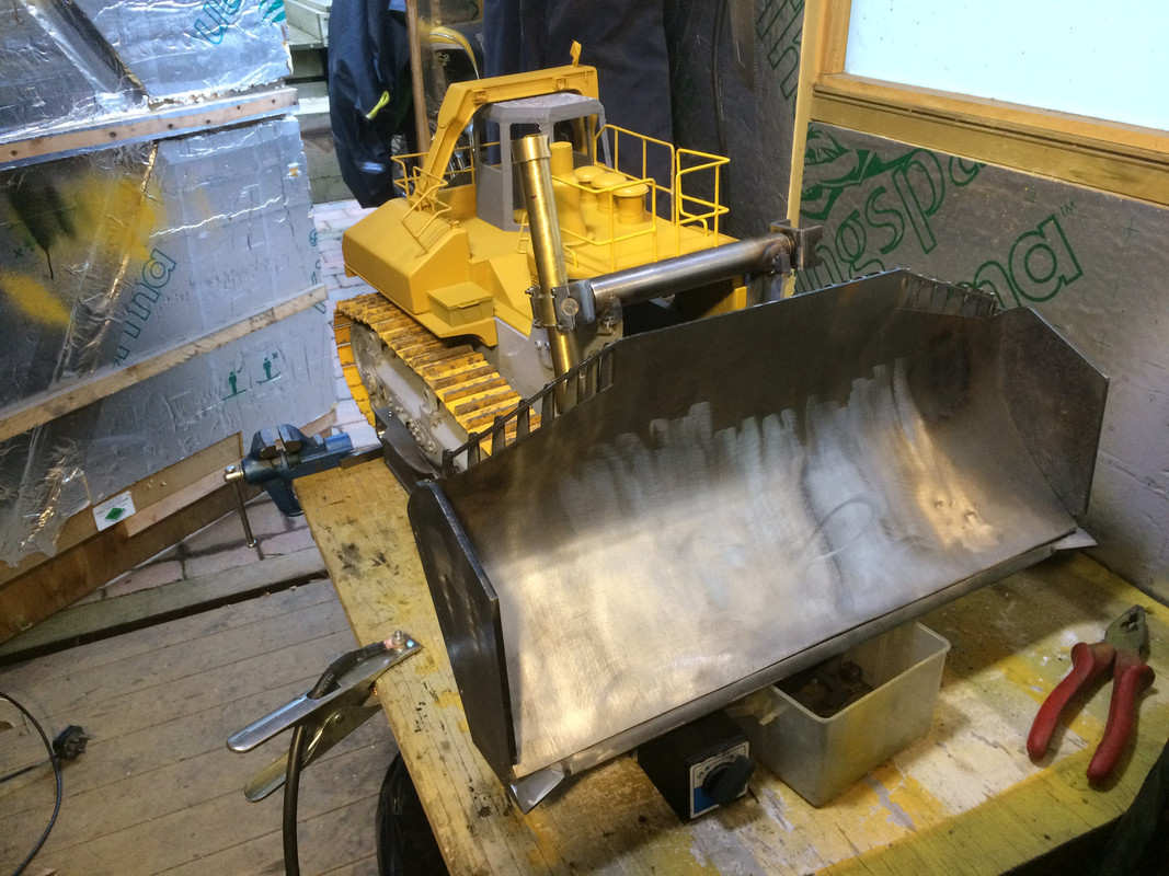   I also had a nice delivery from Premacon so I thought it would be best to put together a pump set that I could test outside the machine for leaks etc then simply bolt in position and connect the rams   https://youtu.be/hY6JiJXL7Pw The weight of the blade is quite a lot and I am concerned that the rams wont lift it !
|
|
#57
03-20-2021, 06:47 AM
|
|||
|
|||
|
So put everything together to see how it works.
The weight of the blade in the raised position seems to move the balance and pivot point towards the front idlers and there is a bit of slack in the tracks when reversing etc. i may need to install some stiffer springs to tension the tracks more and/or install the ripper to add weight to the back which should also balance it out. Happy the rams are up to doing the job though Will try and get some videos of it pushing dirt soon https://youtu.be/F8dfyTtsrY0
|
|
#58
03-20-2021, 10:32 AM
|
||||
|
||||
|
Well done Robert!
Have you weighed it yet?
__________________
Sharing knowledge is one thing that defies basic arithmetic logic --- the more you share, the more you get! Joe
|
|
#59
03-20-2021, 10:33 PM
|
||||
|
||||
|
Being an avid Komatsu guy, this build is great! Detail, proportion, function are just like the real Super Dozer. Congratulations on a successful first hydraulic test.
Ken
__________________
Big iron is awesome!
|
|
#60
03-21-2021, 08:25 AM
|
||||
|
||||
|
Looking forward to see the power of this beast on the dirtpiles!
__________________
Emil G | MFZ Blocher Fendt 926 | RC4WD Volvo EC480 excavator | Carson LR 634 | Kenworth 6x6 hauler | Kenworth 6x6 dtrk My channel: To view links or images in signatures your post count must be 10 or greater. You currently have 0 posts. Construction site on Facebook: To view links or images in signatures your post count must be 10 or greater. You currently have 0 posts. Pictures on Instagram: To view links or images in signatures your post count must be 10 or greater. You currently have 0 posts.
|
|
| Currently Active Users Viewing This Thread: 1 (0 members and 1 guests) | |
| Thread Tools | |
| Display Modes | |
|
|


 Linear Mode

