|
|||||||
| Construction Equipment Tech Hydraulics, Electronics, General Engineering, ect in constr equip |
 |
|
|
Thread Tools | Display Modes |
|
#21
 04-22-2011, 02:22 PM
|
|||
|
|||
|
Hi All just joined.
If any one fancies a roll your own pump switch based on a 12f675 pic and a fet then I can post the code and schematics. The dead band can be easily programmed and the delay time to the pump switch off. The one I have in my excavator works great on 4 hydraulic channels Iain UK 
|
|
#22
04-22-2011, 10:27 PM
|
||||
|
||||
|
Hey Iain, Welcome aboard! Please share your info on the pump controler, New way's to do thing's are alway's appreciated here!
Later, Neil#2 aka doodlebug.
|
|
#23
04-23-2011, 04:01 AM
|
||||
|
||||
|
Same reply as in another thread: As for the Leimbach system, it seems there's little difference in strength when it comes to the pump's speed. Here's a little test I did yesterday: http://www.youtube.com/watch?v=aqNTPp1g4pE
__________________
Emil G | MFZ Blocher Fendt 926 | RC4WD Volvo EC480 excavator | Carson LR 634 | Kenworth 6x6 hauler | Kenworth 6x6 dtrk My channel: To view links or images in signatures your post count must be 10 or greater. You currently have 0 posts. Construction site on Facebook: To view links or images in signatures your post count must be 10 or greater. You currently have 0 posts. Pictures on Instagram: To view links or images in signatures your post count must be 10 or greater. You currently have 0 posts.
|
|
#24
04-24-2011, 05:53 AM
|
|||
|
|||
|
If you look at performance graphs for gear pumps the faster they rotate the greater volume they move which overcomes the internal leakage more and more.
However like most things there is a compromise and they will consume more and more power as they do this.
|
|
#25
04-24-2011, 01:25 PM
|
|||
|
|||
|
hi all
here is the asm code for a pump switch as used in my excavator for a couple of years. Works on a 12f675 pic. I'll try and post a link to video of it working soon. ;============================================= ; written by Iain Dunn ; 2 August 2010 revision release ; version 1.2 PCB EXPRESSPCB main revised3 ; file saved as pumpswitch675.asm ; for 12f675 ; int clock 4MHz ;============================================== ; Description,3 or 4 channel inputs for pump control ; via 1 fet 19N10. ; Input 4 not programmed yet ; ; |----||----| ; | 100n | ; 5v--|-------|----0V ; NC----|12f675 |----in2 GP0 ;GP4pumpout----| |----in1 GP1 ; GP3 in4----|-------|----in3 GP2 ; List P=12f675 ; define processor #INCLUDE <p12f675.inc> ; processor specific definitions ;================================================= ================= ;configuration ;no data protect ;no code protect ;no brown out reset ;no MCLR pin function ;power up timer disabled ;Watchdog timer enabled ;oscillator INTOSC with no CLKOUT __config _CP_OFF & _CPD_OFF & _BODEN_OFF & _MCLRE_OFF & _WDT_ON & _PWRTE_ON & _INTRC_OSC_NOCLKOUT errorlevel -302 ;suppress error 302 radix dec ;everything in decimal ;unless indicated ;========== constants========================================= ============ ;GPIO,1 chan1 GPIO,3 chan 2 all rest outputs #define INPUT_1 1 #define INPUT_2 0 #define INPUT_3 2 #define PUMPOUT GPIO,4 #define minpulse 80 #define lowon 140 #define highon 160 #define maxpulse 220 #define OFFDLAY 20 ; delays switching off pump #define TisBits (1<<INPUT_1)|(1<<INPUT_2)|(1<<INPUT_3) ;========Notes==================================== ======================== ;pulses must be larger than 0.8ms to be valid and less than 2.2ms ;The switching limits are ;1.55 ms upper off 1550us ;1.45 ms lower off 1450us ;==========Variables============================== ======================= cblock 0x20 CHAN_1 ; channel 1 width CHAN_2 ; channel 2 width CHAN_3 ; channel 3 width ARM_PULSES ; stores arm pulse count ARM_1 ; channel 1 arm pulse count ARM_2 ; channel 2 arm pulse count ARM_3 ; channel 3 arm pulse count Dlay Dlay_outer Dlay_inner OffCount ; delays pump switch off for 1/2 second endc ;=========Declarations============================ ======================= org 0 ;first instruction to be executed goto START ;========Initilizations=========================== ======================= INIT clrf GPIO ;clear all outputs for now bsf STATUS, RP0 ; bank 1 call 3FFh ;call osc calibration movwf OSCCAL movlw b'1001010' ;WDT scale 1:4 gives around 72ms movwf OPTION_REG ;before reset movlw TisBits ;GPIO 2,3,5 input GPIO,0,1,4 output movwf TRISIO clrf ANSEL bcf STATUS, RP0 ;bank 0 movlw b'00000111' ;turn off comparator movwf CMCON ;digital i/o clrf T1CON ;turn off timer 1 clrf ADCON0 return ;========== Start of main outer loop of program =============================== START call INIT clrf GPIO clrf CHAN_1 ; clrf CHAN_2 clrf CHAN_3 movlw OFFDLAY movwf OffCount movlw 50 movwf ARM_PULSES clrwdt ;========== wait for 25 valid pulses to arm ===================== ARMING clrf ARM_1 clrf ARM_2 clrf ARM_3 btfss GPIO,INPUT_1 goto $-1 ARMLOOP_1 incf ARM_1,f btfss GPIO,INPUT_1 b ARM2 nop b $+1 b $+1 b ARMLOOP_1 ARM2 btfss GPIO,INPUT_2 goto $-1 ARMLOOP_2 incf ARM_2,f btfss GPIO,INPUT_2 b ARM3 nop b $+1 b $+1 b ARMLOOP_2 ARM3 btfss GPIO,INPUT_3 goto $-1 ARMLOOP_3 incf ARM_3,f btfss GPIO,INPUT_3 b PULSE_1 nop b $+1 b $+1 b ARMLOOP_3 PULSE_1 movlw lowon subwf ARM_1,w ; ARM_1-lowon(148) bnc ARMING movlw highon subwf ARM_1,w ; ARM_1-highon(152) bc ARMING PULSE_2 movlw lowon subwf ARM_2,w ; ARM_2-lowon(148) bnc ARMING movlw highon subwf ARM_2,w ; ARM_2-highon(152) bc ARMING PULSE_3 movlw lowon subwf ARM_3,w ; ARM_3-lowon(148) bnc ARMING movlw highon subwf ARM_3,w ; ARM_3-highon(152) bc ARMING VALID_NEUTRAL clrwdt decfsz ARM_PULSES,f goto ARMING ;========= now armed beep from both motors ========================================== movlw 10 movwf Dlay_outer clrf Dlay_inner PWM_LOOP clrwdt bsf PUMPOUT movlw 10 movwf Dlay decfsz Dlay,f goto $-1 clrf GPIO movlw 100 movwf Dlay decfsz Dlay,f goto $-1 decfsz Dlay_inner,f goto PWM_LOOP decfsz Dlay_outer,f goto PWM_LOOP clrf GPIO ;turn motors off ;========= Wait for channel pulses to start ========================================= RCIN1 clrf CHAN_1 btfss GPIO,INPUT_1 b $-1 LOOP_1 incf CHAN_1,f btfss GPIO,INPUT_1 b RCIN2 nop b $+1 b $+1 b LOOP_1 RCIN2 clrf CHAN_2 btfss GPIO,INPUT_2 b $-1 LOOP_2 incf CHAN_2,f btfss GPIO,INPUT_2 b RCIN3 nop b $+1 b $+1 b LOOP_2 RCIN3 clrf CHAN_3 btfss GPIO,INPUT_3 b $-1 LOOP_3 incf CHAN_3,f btfss GPIO,INPUT_3 b PROCESS_IN_1 nop b $+1 b $+1 b LOOP_3 ;==========process the channel timings ==================================== PROCESS_IN_1 clrwdt movlw minpulse subwf CHAN_1,w ; CHAN_1-minpulse(80) bnc PROCESS_IN_2 movlw maxpulse subwf CHAN_1,w ; CHAN_1-maxpulse(220) bc PROCESS_IN_2 movlw lowon subwf CHAN_1,w ; CHAN_1-lowon(145) bnc PUMP_ON movlw highon subwf CHAN_1,w ; CHAN_1-highon(155) bc PUMP_ON PROCESS_IN_2 movlw minpulse subwf CHAN_2,w ; CHAN_2-minpulse(80) bnc PROCESS_IN_3 movlw maxpulse subwf CHAN_2,w ; CHAN_2-maxpulse(220) bc PROCESS_IN_3 movlw lowon subwf CHAN_2,w ; CHAN_2-lowon(145) bnc PUMP_ON movlw highon subwf CHAN_2,w ; CHAN_2-highon(155) bc PUMP_ON PROCESS_IN_3 movlw minpulse subwf CHAN_3,w ; CHAN_3-minpulse(80) bnc RCIN1 movlw maxpulse subwf CHAN_3,w ; CHAN_3-maxpulse(220) bc RCIN1 movlw lowon subwf CHAN_3,w ; CHAN_3-lowon(145) bnc PUMP_ON movlw highon subwf CHAN_3,w ; CHAN_3-highon(155) bc PUMP_ON PUMP_OFF decfsz OffCount,f b RCIN1 bcf PUMPOUT movlw OFFDLAY movwf OffCount b RCIN1 PUMP_ON bsf PUMPOUT movlw OFFDLAY movwf OffCount b RCIN1 ;============End programme ================================================== ======== return END
|
|
#26
04-25-2011, 05:20 AM
|
|||
|
|||
|
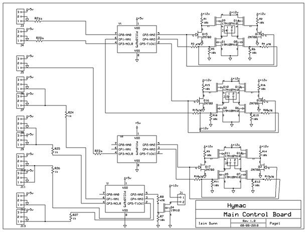
Hi again. just thought I would include a pic of my control board amd circuit diagram. This has 3 speed controllers and the hydraulic pump switch on it. The pump switch is good to about 4 amps without heatsink but can go up to 12 amps with a heatsink.
The pump switch is the bottom PIC chip. Not sure if the diagram will be big enough as an attachment.
|
|
#29
04-25-2011, 01:41 PM
|
||||
|
||||
|
Quote:
So I would think on a small scale model there is no reason why the pump can't be throttled back to reduce heat, and increase battery life. Sounds like a win win situation to me. Heat is the worst enemy for a hydraulic system, next to oil contamination. Yes, you could put a heat exchanger on any hydraulic system, but on a scale model, it would be easier and cheaper to throttle back the pump, or shut it off completely. Out in industry, where I work, we are starting to see some hydraulic pumps run with electric motors, and variable frequency motor drives, which throttle the motor and pump RPM back, when the flow is not needed. The worst is when an operator walks away from a machine and leaves it running. The oil is constantly going over the relief valve and the motor is drawing more power in doing so, while also heating up the oil for the next few hours. Yes, the heat exchangers cool the oil too, but it is still getting warmer then it normally would, if the machine is cycling.
__________________
Nathan
|
|
#30
04-25-2011, 06:49 PM
|
||||
|
||||
|
Nate the cooler and fan are under $30 so I would say it is probably a little cheaper than a speed controller. To me it just seams like a wast of money and time to deal with a simple issue.
Travis
__________________
AKA "00" Biddle RIP FreddyGearDrive 2-12-59/12-19-11
|
|
#31
04-25-2011, 08:57 PM
|
||||
|
||||
|
One thing to consider, the newer John Deere excavator's with "Power Wise" do speed up and slow down depending on hydraulic load. Sound's weird to hear them speed up under heavier load, maybe 2-300 rpm. My neighbor has a 160 Deere, that doe's it. And yes this is separate from the "auto idle" function.
Later, Neil#2 aka doodlebug.
|
|
#32
04-26-2011, 03:03 AM
|
||||
|
||||
|
Quote:
 But you do need a radio with at least 2 free mixes. But you do need a radio with at least 2 free mixes.
__________________
Emil G | MFZ Blocher Fendt 926 | RC4WD Volvo EC480 excavator | Carson LR 634 | Kenworth 6x6 hauler | Kenworth 6x6 dtrk My channel: To view links or images in signatures your post count must be 10 or greater. You currently have 0 posts. Construction site on Facebook: To view links or images in signatures your post count must be 10 or greater. You currently have 0 posts. Pictures on Instagram: To view links or images in signatures your post count must be 10 or greater. You currently have 0 posts.
|
|
#33
04-26-2011, 11:35 AM
|
|||
|
|||
|
Here is a link to short video showing my excavator running with my control board. I have it programmed so when all sticks are neutral hydraulic pumo will switch off after 2 seconds. Hope you find it useful. If you want further details of this board and how to build program one let me know and I'll post otherwise I'll assume it's of no interest.
 Cheers http://www.youtube.com/watch?v=JaDPkz3Z5JA
|
|
#34
04-26-2011, 11:45 AM
|
||||
|
||||
|
Quote:
 looks and works great. looks and works great.Quote:
|
|
#35
04-26-2011, 12:07 PM
|
|||
|
|||
|
A cooler could easily be set up with just the one pump. Placed in the return to tank line from the control valve block and with a low psi bypass around it.
__________________
Jeff
|
|
#37
04-27-2011, 11:11 PM
|
|||
|
|||
|
Hi Iain
is is possible you could share the pic hex files for both the H-Bridge drive pics and the pump switch pic. I can program pic's and a couple local guys would like to play with you design. Thanks for sharing Quote:
|
|
#38
04-28-2011, 09:23 AM
|
|||
|
|||
|
Would you prefer the assembler as you then play around with it in mplab ?
I have posted the assembler for the pump switch above: Below is the speed control based on microchips simple esc desigen but rewritten to give forward and reverse. The track motor controls are on one 12f675 and are simply forward and reverse for both run off toggle switches on my trasnmitter. I did do a 2 speed version but didn't gain much from it: Any questions just ask. Iain
|
|
#39
04-28-2011, 09:59 PM
|
|||
|
|||
|
I am looking to take some shortcuts to start with. So If you have the .hex binary files would save me some time initially. I use Eagle for pcb design and I make prototype pcb's on a small cnc mill built for the purpose.
I have your schematic diagram, could you post an image of the copper side of the pcb? It will save me some layout time. I don't currently have mplab installed anywhere. Looks like I will have to rebuild my development box. Thanks for all your help. Ted Quote:
|
|
#40
04-28-2011, 10:27 PM
|
||||
|
||||
|
Quote:
") Yes I did take offence! Yes I did take offence!I work for the CAT Rental Store and work on all kinds of hyd systems by a lot of different manufactures JLG, Broderson, LULL, Bell, Trail King, and the list goes on but hay my boss will be glad you explained to me how it works. All I am saying is why over complicate some thing you can take care of with a cheap switch or cooler. Quote:
Travis
__________________
AKA "00" Biddle RIP FreddyGearDrive 2-12-59/12-19-11
|
|
| Currently Active Users Viewing This Thread: 2 (0 members and 2 guests) | |
| Thread Tools | |
| Display Modes | |
|
|


 Linear Mode

