|
|||||||
| Highway Trucks and Trailers On road trucks and trailers single and twin axle trucks. |
 |
|
|
Thread Tools | Display Modes |
|
|
|
#1
 09-03-2021, 08:29 PM
|
|||
|
|||
|
Quote:
And M3.5? Who thought of that? Sheesh. I bow to your successful use of the N20's. I've only recently looked at them as I've previously used the 9gs, but the gearing coupled with the even smaller size is attractive. Wrt lighting, one word: Arduino. Yes, you gotta learn a bit of "programming", but there are a bazillion tutorials on the web so it's not a word to be afraid of. Also, they are just MADE for this sort of thing; they drive LED's almost directly (fine, you need a resistor), and can come in fairly tiny form factors. I don't know your TX setup well, but mine sends out all of its channels on essentially an RS232 serial bus, ie like those on a computer, so it's easy to make work with the Arduino. Then you just read the channels, and say something like if (channel[1] < 1450) {turnonLED(left);} // left turn else if (channel[1] > 1550) {turnonLED(right);} // right turn else {turnoffLED(left); turnoffLED(right);} total psuedocode, not exactly how it's written, but you get the idea. The deadband of 1450...1550 in the middle lets the stick float a little before doing the lights. If your stick is hyperaccurate you can turn it down to 1495...1505 or whatever (see below about making changes via pushing buttons!  ) )If instead it's auxiliary lights on a switch, you just do if (channel[6] > 1750) {turnonLED(aux);} // switch on else {turnoffLED(aux);} // switch off Blinking is a bit more complicated, but you start simple and work your way up. The key thing in my mind is that once you get the 'dweeno and the LED's set up, the rest is done in software, so if you want to add new features or blink patterns or whatever, you don't have to swap out the board, just USB it to your computer and upload the new code. I tend to use these guys https://www.arduino.cc/en/pmwiki.php...noBoardProMini They're about 0.7" x 1.3" (err, 18x33mm), and the generic ones are a coupla bucks per, especially if you get a multipack. They'll run right off a 2S LiPo, or the RX BEC if you're using 3S+. They can drive servos directly, easy peasy, and like I said LED's just need one resistor, so the basic RC stuff is a breeze. There are smaller boards if you're that tight for space, but you tend to lose functionality as they don't have room for connections for the fun stuff. Anyway, I'll stop proselytizing now =)) but feel free to inquire if you're interested. (Also I think some of my build threads have more detail as they use one or multiple Arduinos.) -- A
__________________
I mean, how hard can it be? Last edited by dremu; 09-03-2021 at 08:34 PM. 
|
|
#2
09-04-2021, 06:52 PM
|
|||
|
|||
|
Quote:
|
|
#3
09-05-2021, 04:38 PM
|
|||
|
|||
|
Bruder Piggyback Forklift Build part 5
I'll start this posting off by installing the lead screw. In the previous post there was a photo showing 5 of the parts that can be used for this conversion from Thingiverse. The originator of these parts did not incorporate any way to secure the lead screw to the mounting piece that goes on top of the upper mast assembly. Looking at the photos of his build he posted on Facebook he simply just glued the lead screw to the top of the mount with a blob of some kind of adhesive. This is the one thing about his build that I really did not like. I decided to make my lead screw mount out of 1/4" aluminum bar stock. Photo shows the top of the upper mast, the 3D printed part from thingiverse and the aluminum bar stock I used to make my mount. I used my milling machine to make this part but I've made similar parts in the past with a fine tooth hacksaw, files and a little patience. I used the same dimensions as the 3D printed part except I did not add the boss in the top center. What I added was to cross drill through the center hole and tap for two set screws, one from each side. These would hold the lead screw in position and keep it from turning. [img] 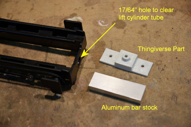 [/img] [/img]The hole you see in the top of the mast was sized to allow the 1/4" tubing being used for the lift cylinder to extend through to the bottom of the lead screw mount. The hole was located using the 3D printed part as a guide by holding it in position on the top of the mast and sliding a transfer punch through the center hole. This photo shows the lead screw mount secured in place at the top of the upper mast. [img] 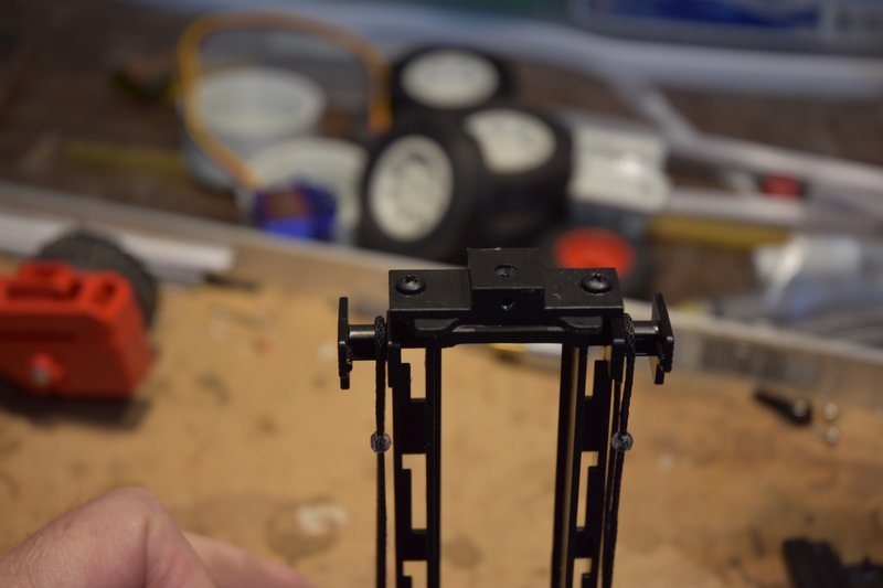 [/img] [/img]Next is to determine the length of lead screw needed. To do this I put the upper mast back on the lower mast and placed the assembly back on the lower body. I blocked up the rear of the body to match the height of the original toy and set the forks to the same level. [img] 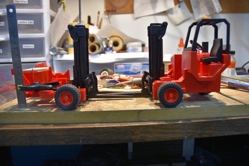 [/img] [/img]Then I ran the lead screw down through the top of the mount, down though the cylinder until if hit the top of the gear box shaft at the bottom of the cylinder. Unscrewed back about 1/2 turn and marked the lead screw at the top of the mount. This is where the excess screw needed to be cut off. [img] 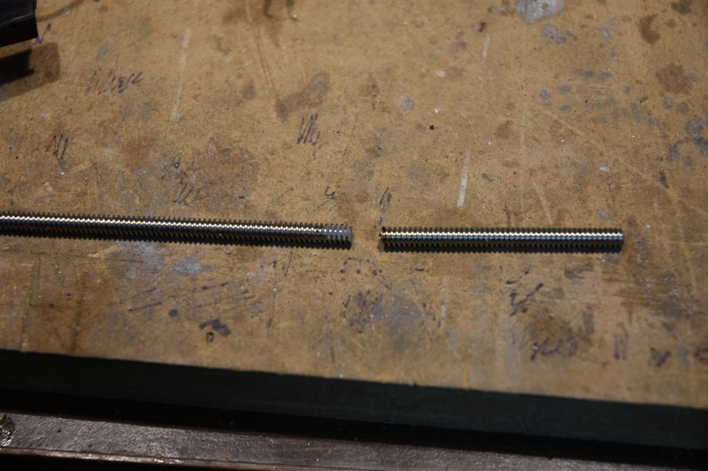 [/img] [/img]After cutting the excess off I filed two flats on the end of the screw for the set screws in the top mount to bear against and keep the lead screw from turning. BTW: one big benefit of having my parts assembled with screws as opposed to gluing them, it is relatively easy to remove the lift motor, cylinder and lead screw to check fits and make adjustments. I bet I had these parts in and out a couple of dozen times during the conversion. Next comes the real fun, the limit switches. The fourth photo of my last post shows some of the parts in the Thingiverse files. We need the part in the lower right called 'ups_tipper'. This part actually serves two purposes. The back side will hold the servo for tipping the mast forward and backwards. The front side serves as the mounting plate for the limit switches. Start by cutting some plastic away at the top of the bottom mast section. The red dashed lines in the photo below show where to cut. [img] 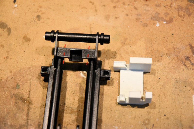 [/img] [/img]And here is the lower mast with the plastic cut out. [img] 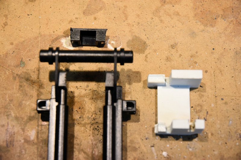 [/img] [/img]The printed part fits in as shown. The curved portions of the part should fit on the curved sections of the mast which I guess are supposed to represent hydraulic cylinders. [img] 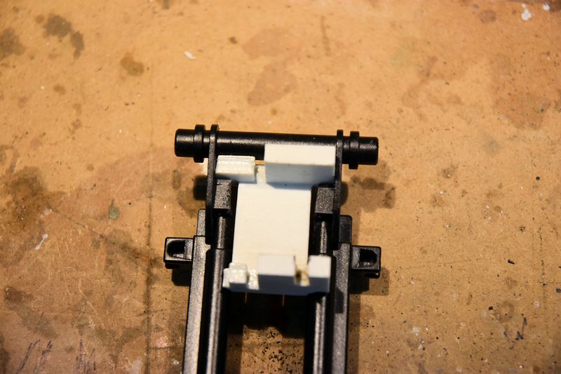 [/img] [/img]This is what the front of the lower mast looks like with the printed part in place. [img] 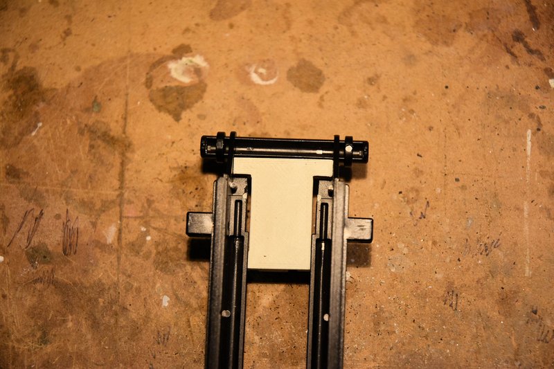 [/img] [/img]Fortunately for me I did not glue this part in place. I thought it might be a good idea to check the fit of the switches I was going to use and make sure they would fit between the mounting plate and the lift cylinder. They did not!!! I was using the same size/type switches that the originator of the parts files used. These are 2A mini snap switches and are about 5.8mm thick. After some head scratching the cause of the problem was obvious. The printed cylinder is much smaller in diameter than the 1/4" brass tubing I used to make my cylinder. If you use the printed cylinder and other parts and the same type of switch you probably won't have this problem, but check the fit before gluing anything in place. How to fix. I wasn't going to scrap the brass cylinder. What I decided to do was redesign and print a new mounting plate. After a lot of careful measuring I determined I needed about 2mm more clearance between the mounting plate and the backside of the cylinder. I basically copied the original part but extended the mounting posts by 2mm. I also added a notch to the servo side to clear the servo wires as the micro servo I was going to use had it's cable exiting the body about half way down it's length instead of at the bottom like the mount was designed for. I next found another problem. By moving the switches back 2mm their arms would no longer hit the parts of the upper mast assembly they needed to hit in order to operate. The fix for the top switch (which stops the lift motor as it lowers the mast) was to simply glue on a piece of styrene at the top back of the upper mast extending the contact point back to where it will hit the switch arm. It was left taller than needed and will be filed down to tune the stopping point later. [img] 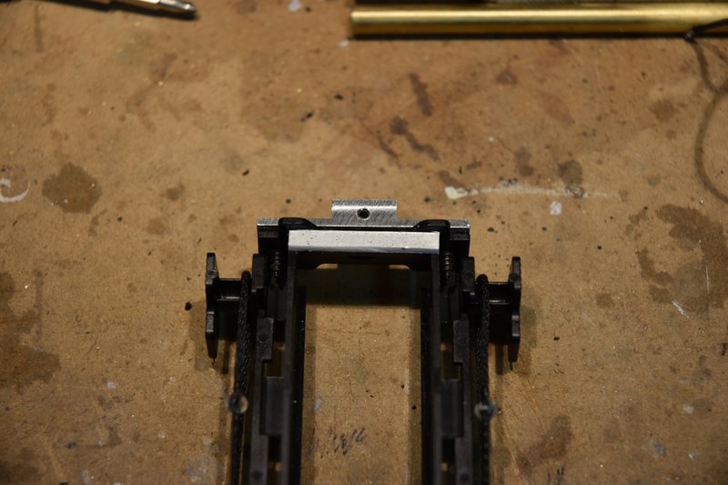 [/img] [/img]The fix for the bottom switch (which stops the lift motor as it raises the mast) was a bit more complicated. First I glued in a square piece of styrene that went across the inside of the left upper mast frame. It sits right on top of the part I had to cut plastic from to clear the round head screws I used to mount the lift motor. NOTE: even if you use the 3D printed parts, if you use round head screws for mounting the motor you may have to do this same procedure for the lower switch. I also had to file away some the plastic I added at the front to clear the fork mount. [img] 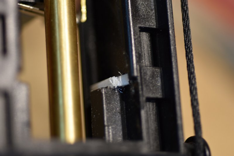 [/img] [/img]I then had to modify the arm on the switch as it's position would be too low to hit the plastic trip bar I just added. I cut and shaped an extension to solder onto the end of the switch arm. And truthfully I just eyeballed it's length and shape knowing that I would have to reshape and adjust it's position when fine tuning. Finally, just to make sure the switches would fit I sanded both sides of each switch to make them just a little thinner. Have to be careful that you don't take too much off or the latches that hold the switches together will fail. This photo shows both switches prior to being installed. [img] 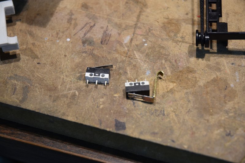 [/img] [/img]
|
|
#4
09-05-2021, 04:42 PM
|
|||
|
|||
|
Bruder Piggyback Forklift Build part 5b
(Had to split this post because of posting size limitations) I glued both switches to the mounting plate in positions shown. The switch on the left will be on the bottom when installed in the mast. When cured I soldered diodes and a jumper wire in place. I used 1N4003 diodes which are rated for 1A which is plenty for these little N20 motors. Then tested the switches to make sure the circuit worked properly. [img] 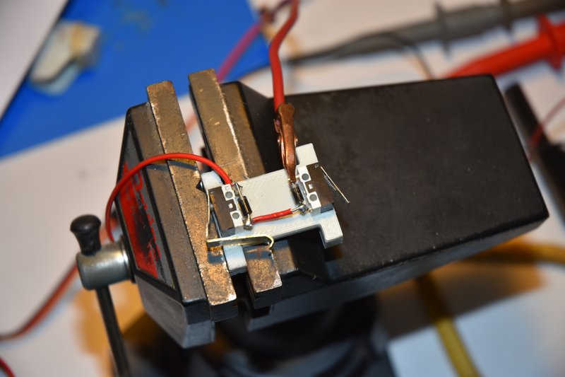 [/img] [/img]At this point I was now ready to glue the switch mounting plate into position at the top of the lower mast. I used a 2 part epoxy for this. While the epoxy was curing I wired up the lift motor with extra long leads that could be trimmed as needed later. The red wire will go up to the limit switches and the black will go to the motor ESC in the body of the lift. [img]  [/img] [/img]Next was to run a longer than needed wire into the bottom backside of the lower mast and run it up the right side of the mast to the switches. The lift motor was reinstalled and it's red wire was also run up the right side to the switches. I cut a small notch in the side of the mast even with both switch's lugs and bent one wire over to each switch and soldered into place as shown. [img] 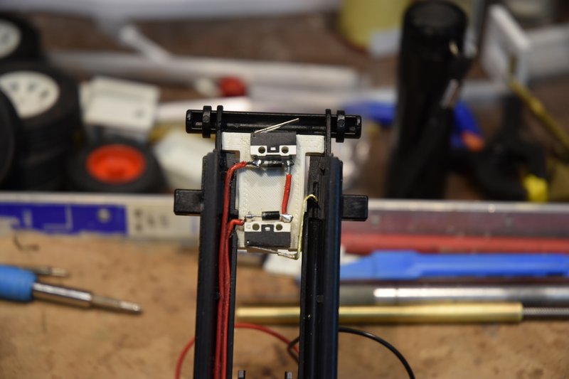 [/img] [/img]This photo shows the lower mast assembly with the lift motor and completed limit switch mount and wiring in place. Big sigh of relief. [img] 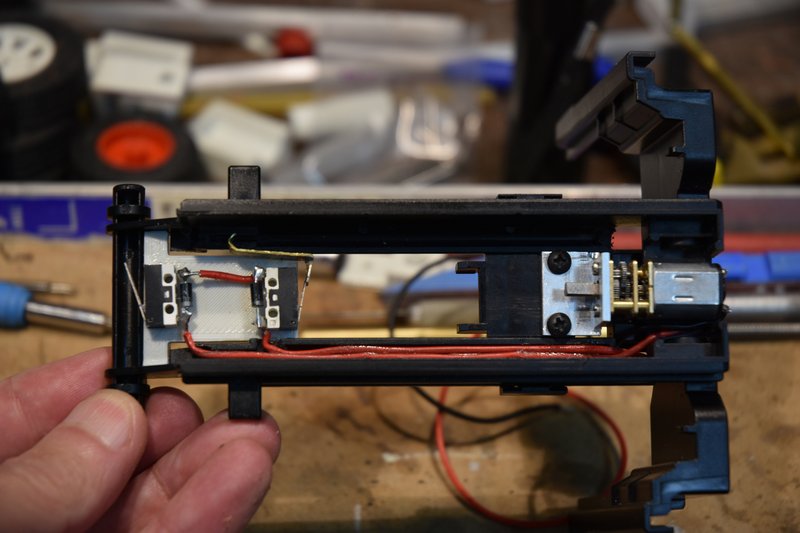 [/img] [/img]The only thing left was to fine tune the activation of the limit switches. Put the upper mast assembly back into position in the lower mast and installed the lift cylinder. Connected a temporary power supply to the wires from the lift motor and started running the mast up and down. Adjusting the top switch was fairly easy. After lowering the mast till it came to a stop, check the position and if was still a little high just sand a little bit more off the bottom of the trip plate on the top of the upper mast. It ended up looking like this. [img] 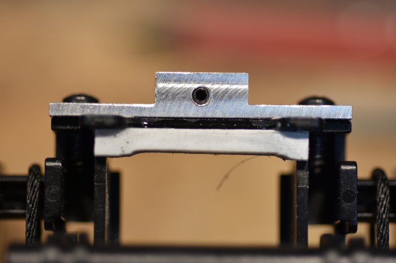 [/img] [/img]Adjusting the action of the lower switch was a bit trickier. I started with the end of the extension I added to the switch arm bent a bit lower than where I knew it needed to be. Raise the upper mast and see where it would stop. Then carefully reach in with a set of needle nose pliers and/or needle file and carefully make a small adjustment to the bend or length of the hook and try again. Took some time but eventually got there. Really big sigh of relief. [img] 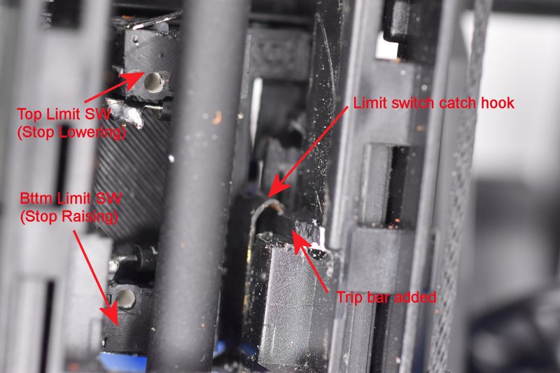 [/img] [/img]I will admit to another error I made. If you look closely at the last photo and the one showing the limit switches mounted at the top of the mast above you might notice that the polarity band on the diodes have changed position. Apparently because I used two red wires up the mast to the switches I didn't pay enough attention to which was which and I got them backwards. The wire to the lower switch was now too short to reach the upper switch so I couldn't just swap them so I had to swap the diodes end for end. Since they were already mounted that meant the swap had to be done with them inside the mast. Not much room for error with a hot soldering iron. Pay attention! Here is a photo of the completed mast lift assembly from the front; [img]  [/img] [/img]and the back. [img] 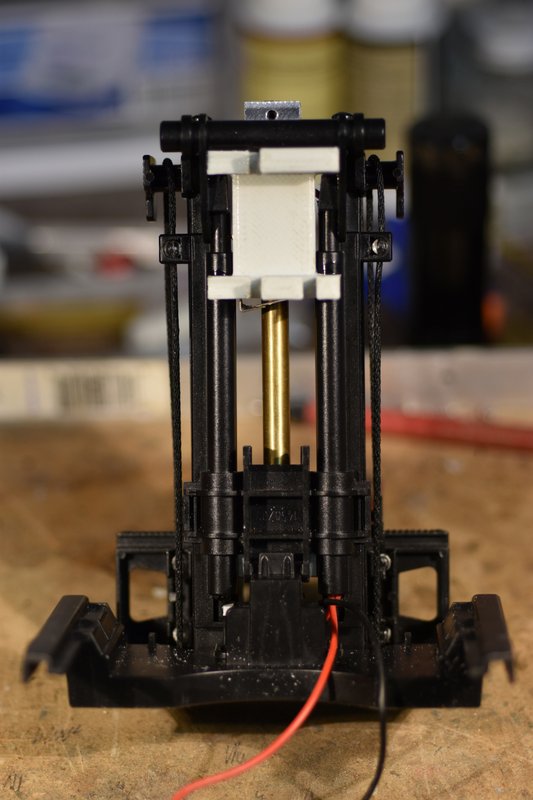 [/img] [/img]That's all for now. In the next part I'll show how the mast tilt assembly goes together.
|
|
#5
09-05-2021, 09:53 PM
|
|||
|
|||
|
Quote:
Wrt the current limit, though, I just drive one LED per pin, and haven't had any trouble at 20mA. Cuts down on component count, but as you say, room is still at a premium. I know Adafruit has their Trinket line that are tiny, or maybe you could just use a bare '328 chip, but then you need a voltage regulator and at least a connection to program it ... ugh. Anyway, I'll stop going off topic, and just say wow. I'm particularly interested in the limit switches as I wanna do something similar for a telescoping column for another project and I have a box of those very switches awaiting the time and work. -- A
__________________
I mean, how hard can it be?
|
|
#6
09-06-2021, 11:16 AM
|
|||
|
|||
|
Quote:
I love Adafruit, they are a great company to deal with. I use a lot of their components. I really like that they are in the US and manufacture a lot of what they sell in house. With the limit switches you just have to pay attention to polarity of diodes, as apparently I did not as noted in last post. For those not familiar with these limit circuits I should have mentioned also that these types of switches have both a Normal Open (NO) and a Normal Closed (NC) circuit which is usually shown on the side of the switch right above the pins. There are usually 3 pins or lugs for wiring, one is a common, one for the NO circuit and one for the NC circuit. For limiting motion of motor drives we want to use the NC circuit. On the switches I used that is the outside two pins. I cut away the third pin to avoid confusion later and a small diode will fit nicely into the space left. There are numerous utube videos detailing how to make these circuits and how they work.
|
|
#7
09-06-2021, 01:49 PM
|
|||
|
|||
|
Bruder Piggyback Forklift Build part 6
Ok, that is the worst of the actual mechanical part of the build. In this part I'll show how I installed the mast tilting capability. It's pretty simple and straight forward. The first step was to take a knife and shave off the nub that engages the detents at the base of the mast that are used to hold the mast in it's manually tilted positions. There is one on each side. We want the mast to freely tilt back and forth. 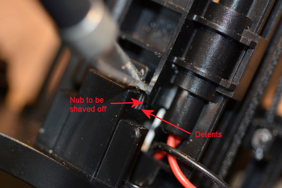 The tilt mechanism uses a standard 9gr micro servo. We already installed the mounting bracket as it is the backside of the limit switch mounting plate. Install the servo and train the cable down the back right side of the mast. The mounting plate from the Thingiverse files is designed for a servo that has it's cable coming out at the bottom of the servo. If you servo is like mine with the cable coming out the side just cut a slot in the mount in the appropriate place.  I like to use ball connectors when making up linkages as they eliminate almost all slop. I had some very small connectors that were salvaged from an old helicopter that I used here. Larger ball connectors, clevis links or even Z-bends could be used. Just try to keep the linkage as tight as possible. I mounted the bottom connector at the rear of the mast base down near the bottom as shown below. Simply drilled appropriate size hole and screwed the ball in place. 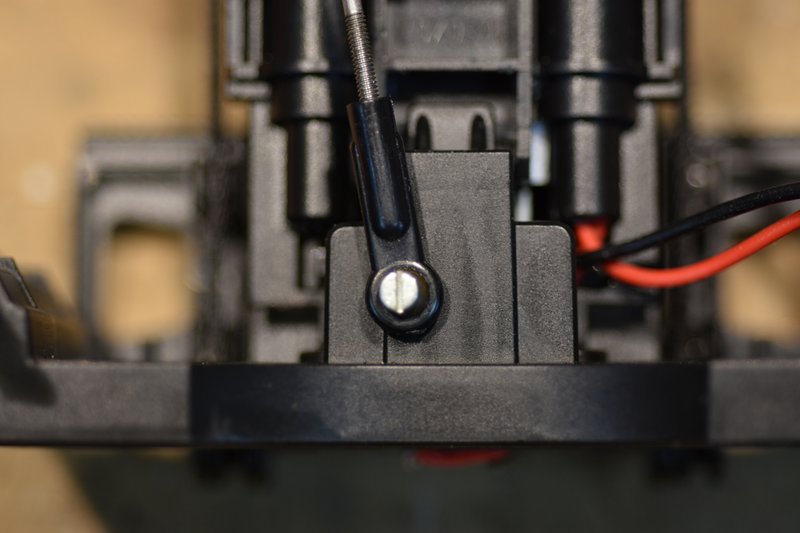 It takes very little servo arm movement to make the mast tilt back and forth. So I cut the servo arm back to one hole and installed a ball connector to the arm. Installed the arm on the servo pointing straight back after making sure the servo was centered. Measured the distance between the two connectors with the mast standing straight up and made up the appropriate length connecting rod.  Here's an overall view of the completed linkage.  The final step was to make a small clip and screw it to the mast base to hold the servo cable and lift motor leads in place. 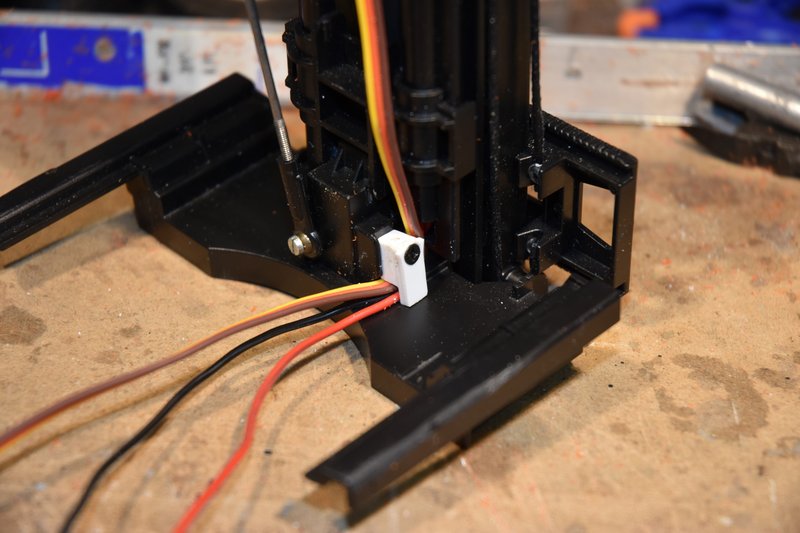 That's it! I mentioned above that it takes very little movement of the servo arm to tilt the mast back and forth and in truth the design of the mast does not allow for a lot of motion. So to prevent over stressing the tilt mechanism at it's limits I have my transmitter end points set to plus and minus 30 percent on this channel. Next post I think I'll do some body work.
|
|
| Currently Active Users Viewing This Thread: 1 (0 members and 1 guests) | |
|
|


 Hybrid Mode
