|
|||||||
| Highway Trucks and Trailers On road trucks and trailers single and twin axle trucks. |
 |
|
|
Thread Tools | Display Modes |
|
|
|
#1
 09-05-2021, 09:53 PM
|
|||
|
|||
|
Quote:
Wrt the current limit, though, I just drive one LED per pin, and haven't had any trouble at 20mA. Cuts down on component count, but as you say, room is still at a premium. I know Adafruit has their Trinket line that are tiny, or maybe you could just use a bare '328 chip, but then you need a voltage regulator and at least a connection to program it ... ugh. Anyway, I'll stop going off topic, and just say wow. I'm particularly interested in the limit switches as I wanna do something similar for a telescoping column for another project and I have a box of those very switches awaiting the time and work. -- A
__________________
I mean, how hard can it be? 
|
|
#2
09-06-2021, 11:16 AM
|
|||
|
|||
|
Quote:
I love Adafruit, they are a great company to deal with. I use a lot of their components. I really like that they are in the US and manufacture a lot of what they sell in house. With the limit switches you just have to pay attention to polarity of diodes, as apparently I did not as noted in last post. For those not familiar with these limit circuits I should have mentioned also that these types of switches have both a Normal Open (NO) and a Normal Closed (NC) circuit which is usually shown on the side of the switch right above the pins. There are usually 3 pins or lugs for wiring, one is a common, one for the NO circuit and one for the NC circuit. For limiting motion of motor drives we want to use the NC circuit. On the switches I used that is the outside two pins. I cut away the third pin to avoid confusion later and a small diode will fit nicely into the space left. There are numerous utube videos detailing how to make these circuits and how they work.
|
|
#3
09-06-2021, 01:49 PM
|
|||
|
|||
|
Bruder Piggyback Forklift Build part 6
Ok, that is the worst of the actual mechanical part of the build. In this part I'll show how I installed the mast tilting capability. It's pretty simple and straight forward. The first step was to take a knife and shave off the nub that engages the detents at the base of the mast that are used to hold the mast in it's manually tilted positions. There is one on each side. We want the mast to freely tilt back and forth. 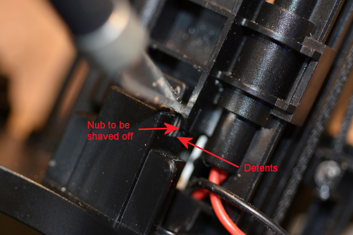 The tilt mechanism uses a standard 9gr micro servo. We already installed the mounting bracket as it is the backside of the limit switch mounting plate. Install the servo and train the cable down the back right side of the mast. The mounting plate from the Thingiverse files is designed for a servo that has it's cable coming out at the bottom of the servo. If you servo is like mine with the cable coming out the side just cut a slot in the mount in the appropriate place.  I like to use ball connectors when making up linkages as they eliminate almost all slop. I had some very small connectors that were salvaged from an old helicopter that I used here. Larger ball connectors, clevis links or even Z-bends could be used. Just try to keep the linkage as tight as possible. I mounted the bottom connector at the rear of the mast base down near the bottom as shown below. Simply drilled appropriate size hole and screwed the ball in place. 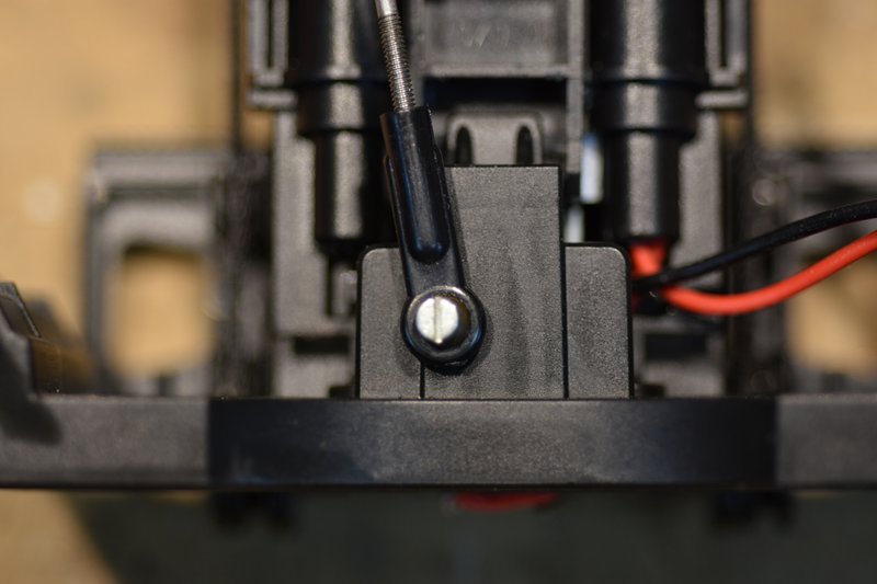 It takes very little servo arm movement to make the mast tilt back and forth. So I cut the servo arm back to one hole and installed a ball connector to the arm. Installed the arm on the servo pointing straight back after making sure the servo was centered. Measured the distance between the two connectors with the mast standing straight up and made up the appropriate length connecting rod.  Here's an overall view of the completed linkage.  The final step was to make a small clip and screw it to the mast base to hold the servo cable and lift motor leads in place. 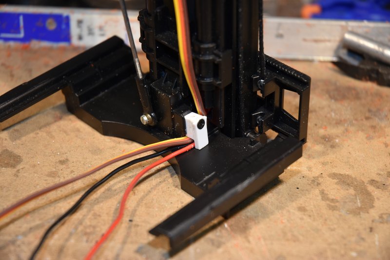 That's it! I mentioned above that it takes very little movement of the servo arm to tilt the mast back and forth and in truth the design of the mast does not allow for a lot of motion. So to prevent over stressing the tilt mechanism at it's limits I have my transmitter end points set to plus and minus 30 percent on this channel. Next post I think I'll do some body work.
|
|
| Currently Active Users Viewing This Thread: 1 (0 members and 1 guests) | |
|
|


 Hybrid Mode
