
 |
|
|||||||
| Euro Style Trucks and Trailers A place for the Euro style trucks single and twin axle trucks and trailers... |
 |
|
|
Thread Tools | Display Modes |
|
#41
|
||||
|
||||
|
Hi Ap, that's good to know! Some of their stuff is pretty nice.
Here meanwhile ... got a bit better at getting screws into small holes, but now a minor set back because of a paint issue. When I took the supports off the frame, the paint stuck to them ... so now have to go and find another overpriced rattle can of cheap paint. (only variety to be found here) 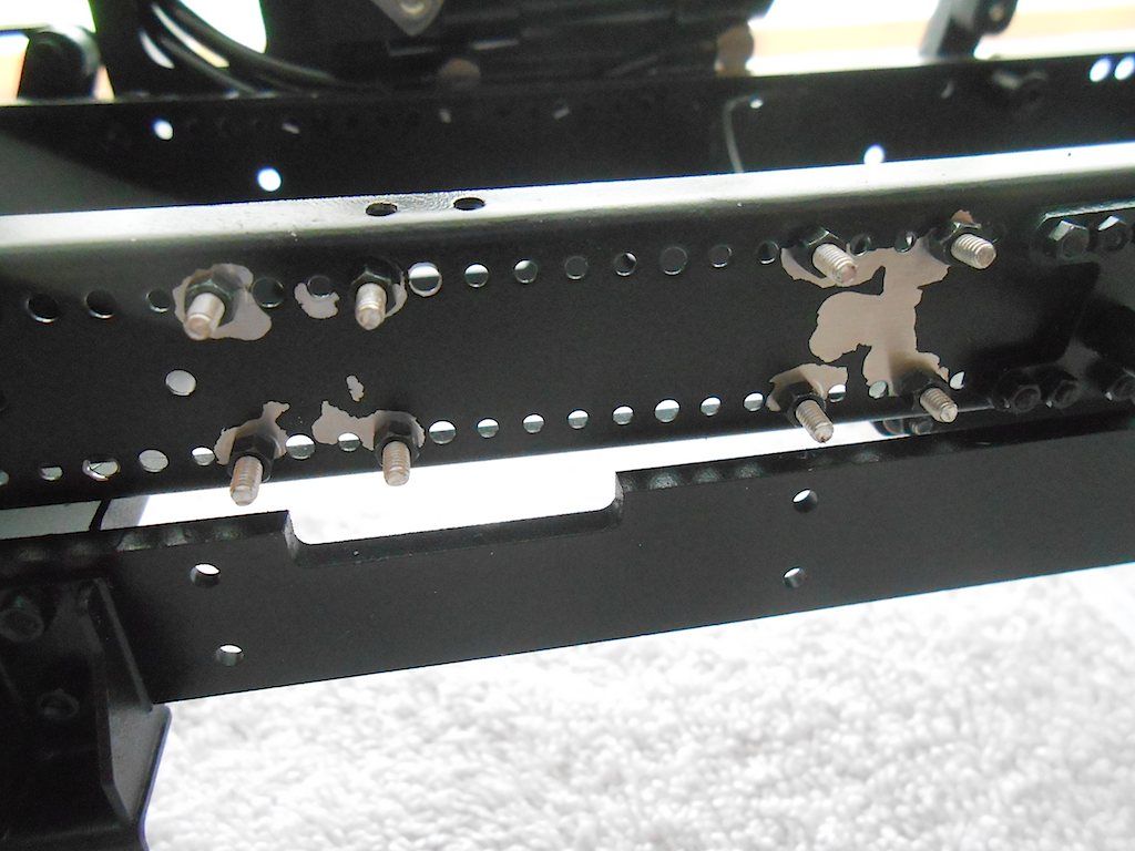 Maybe more tomorrow Cheers, Stephan |
|
#42
|
||||
|
||||
|
OK, was lucky and the local hardware store had one in stock. Masked the area with some paper, couple of shots to paint and we're back in business.
Decided not to move the support because the next opening over is where the frame flares out. I think I would be buying more trouble further in the build. 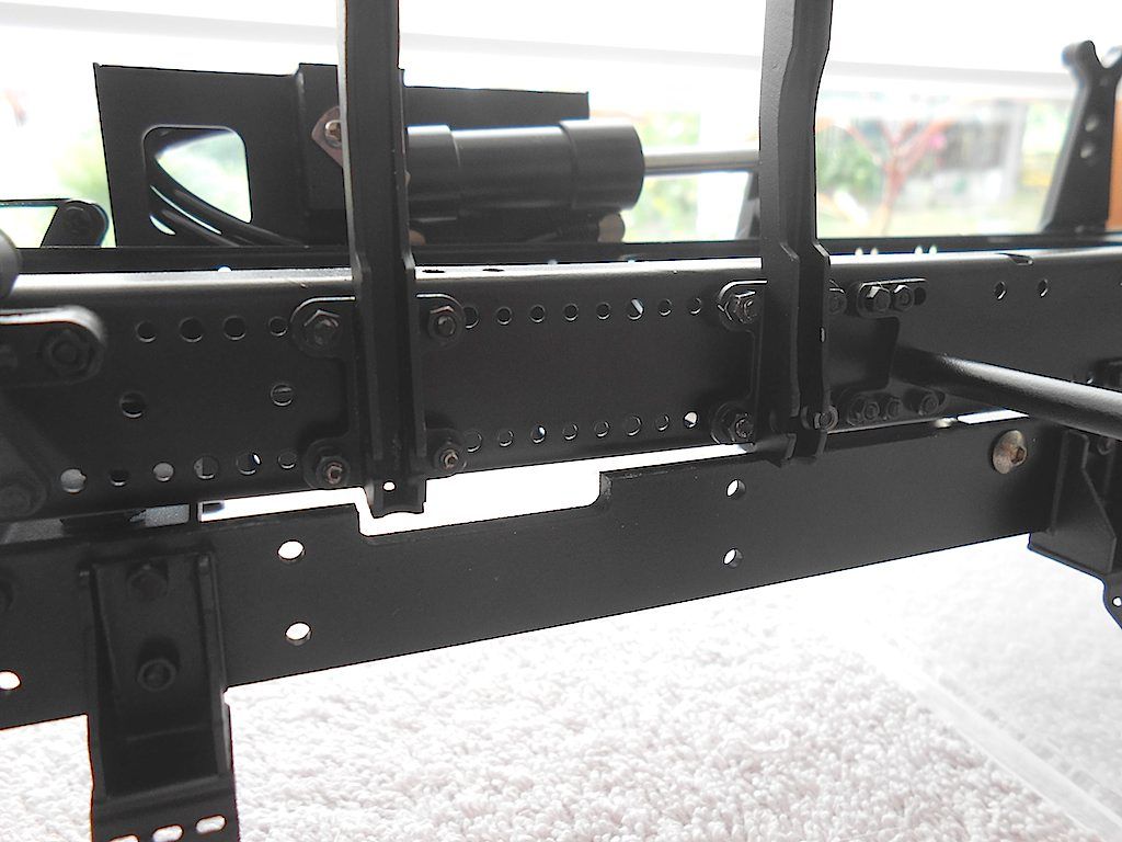 Cheers, hopefully next update more progress. Stephan |
|
#43
|
||||
|
||||
|
Some progress. Got both front axles and the steering linkage installed
 The steering linkage from 1st to 2nd front axle went on first. This serves to make the radius of the turn slightly different for each axle. The actual rod connecting the two is just some threaded rod stuck in a messing tube with the two clamps screwed on. Had assembled it for painting purposes. 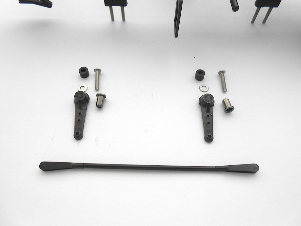 Easier to first put the linkage on the steering levers first. That clamp is tight and takes some force to slip on. Highest point on the front axle, lowest on the second. 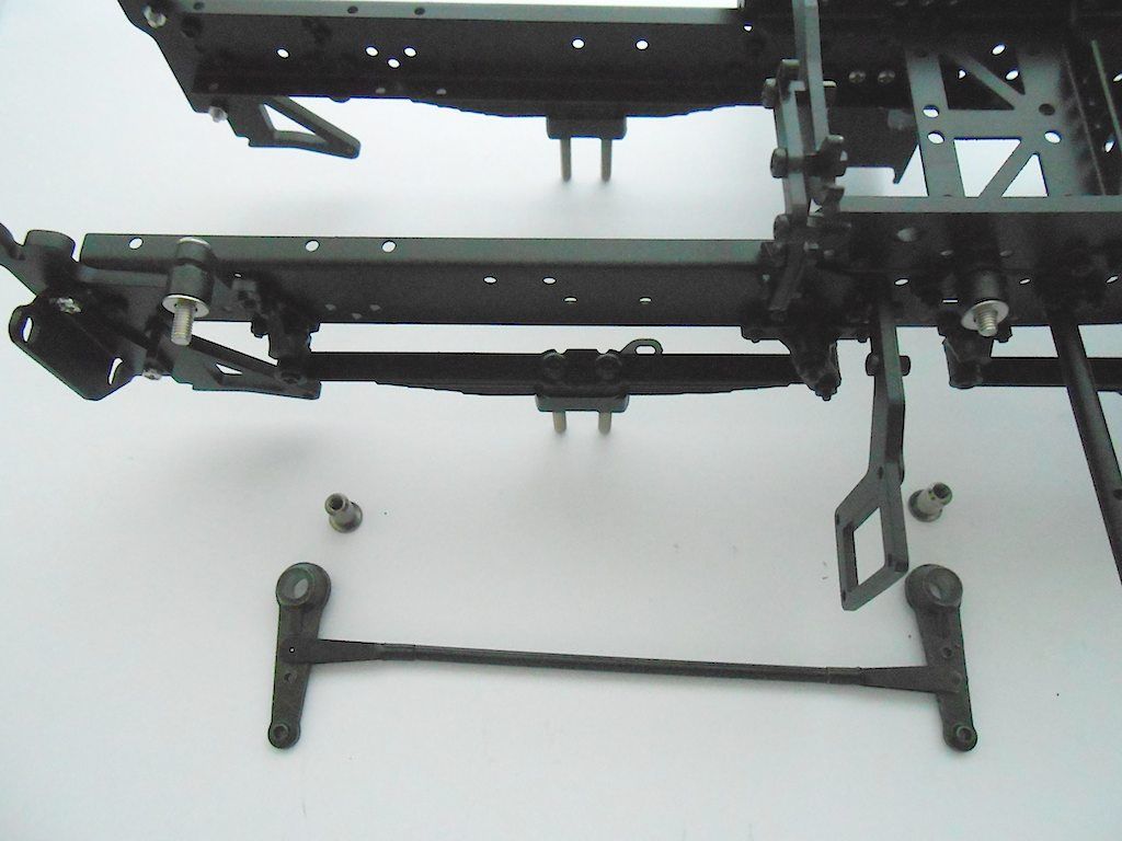 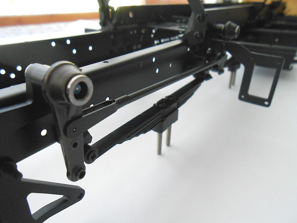 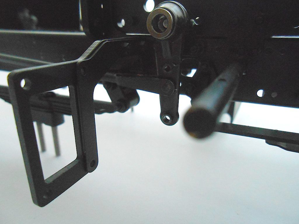 Now the front axle. A very hefty piece (put it on the kitchen scales and came in at 278 grams) and beautifully finished. 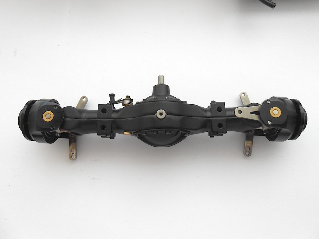 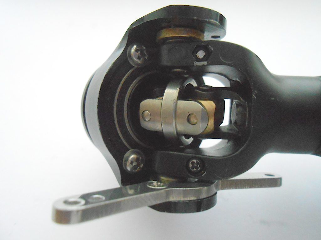 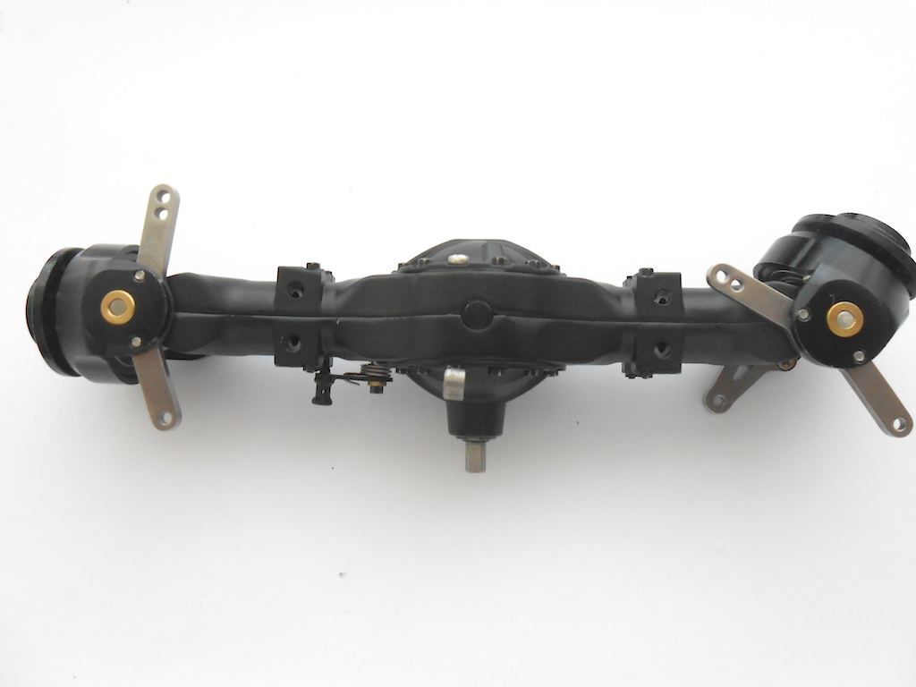 Here with the components of the track rod. The little M2x5 screw I put in the opening on top to prevent dirt getting in. (not in the manual, but someone on one of the German forums mentioned it was a good preventive thing to do) 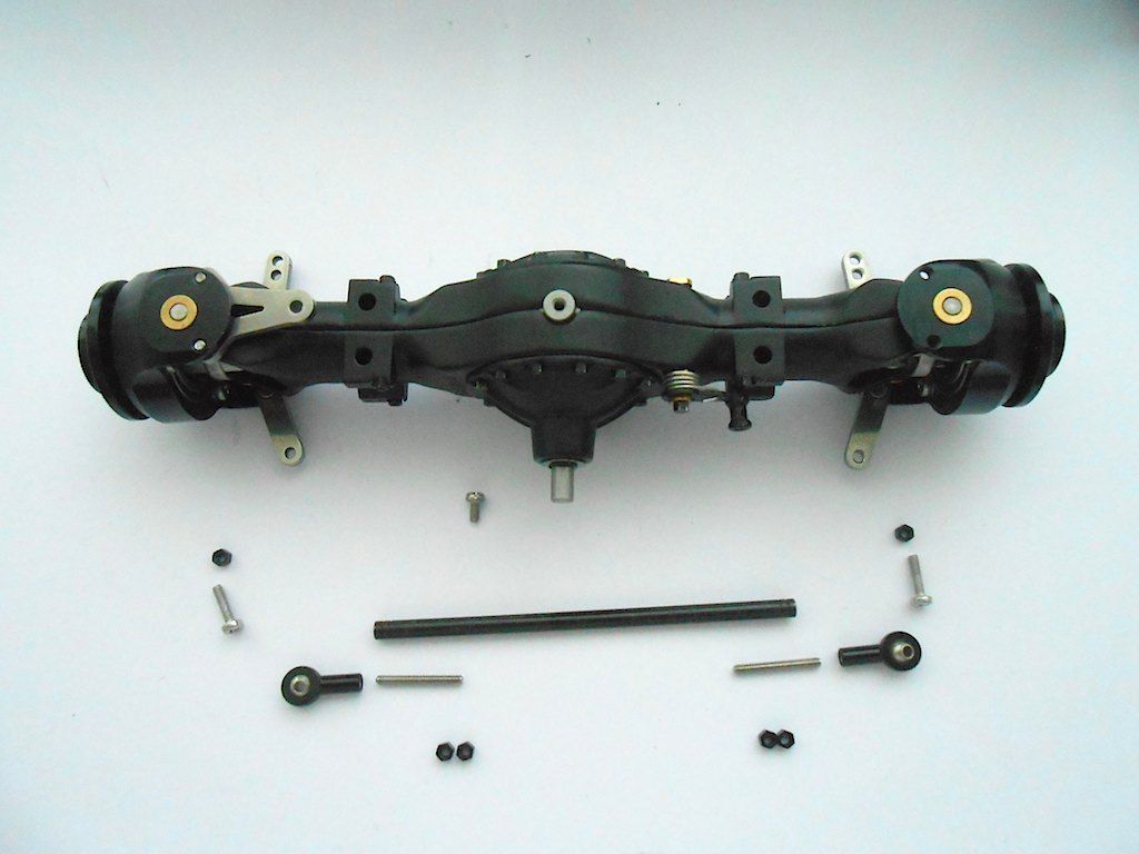 Track rod goes on top on the first axle 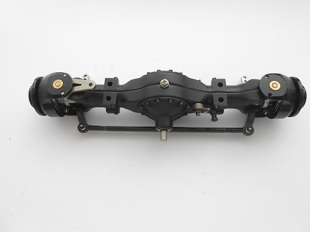 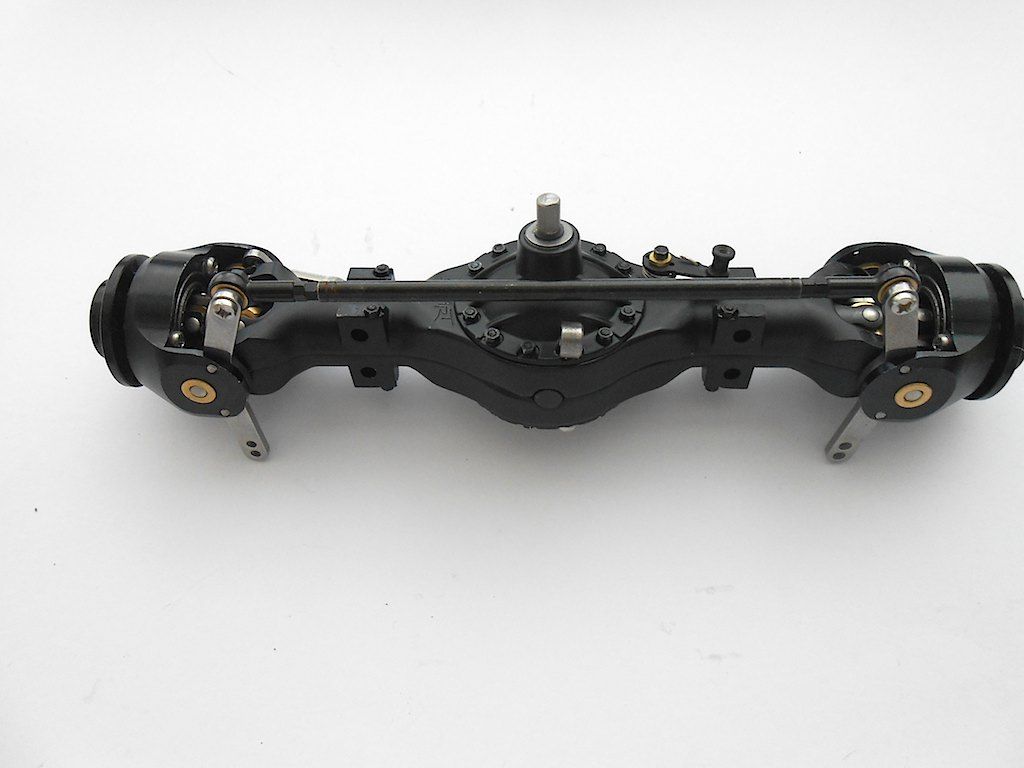 Added some bling to the axle. There are little holes in there, and you ScaleART has miniature hex heads that can be put in there (not part of the kit). You will have to drill the hole out to 1 mm and then you can tap them in with one of those hard plastic hammers. Bit tedious but looks good when finished. 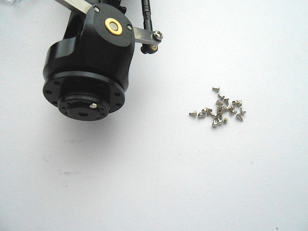 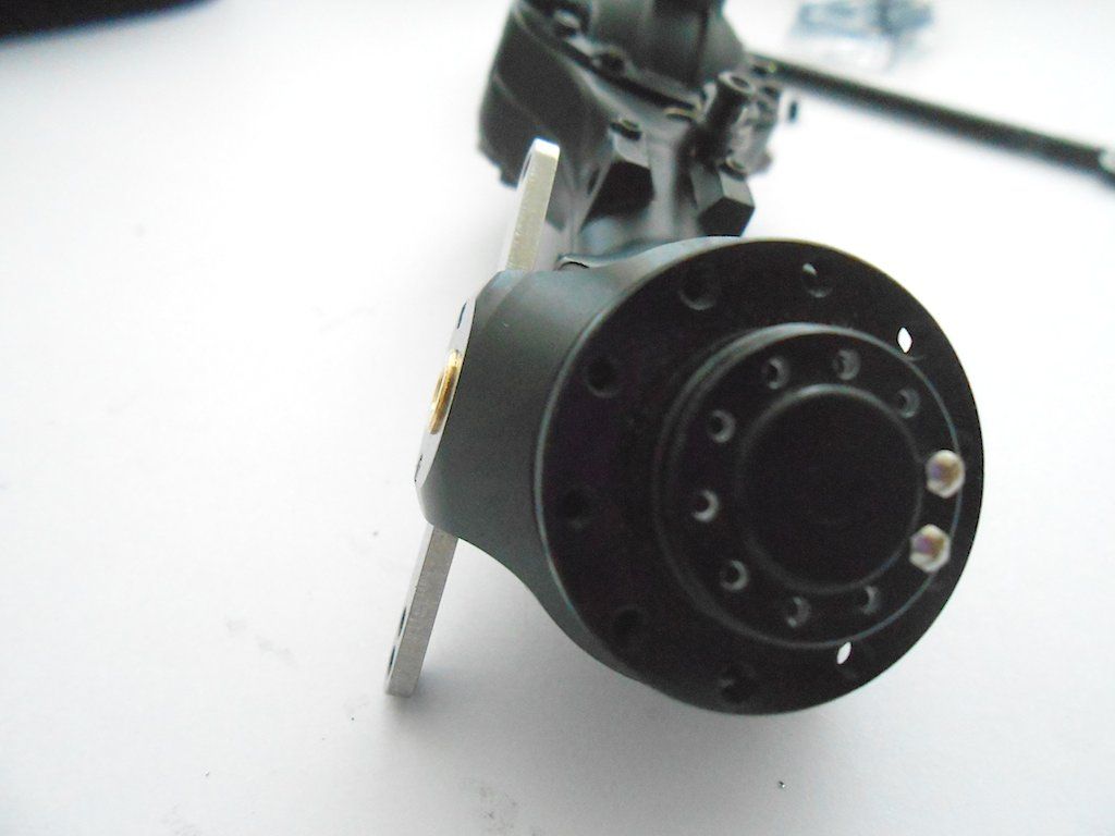 Then slide axle on the suspension and bolt up. You need a 5.5 key for those nuts. 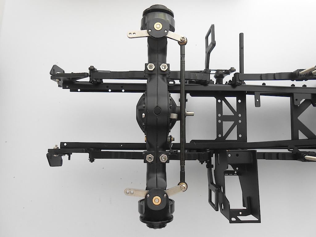 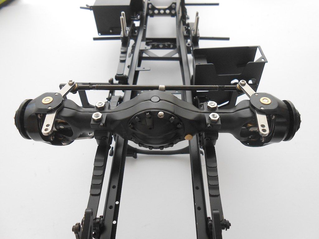 Then we need a lever to connect the steering to the axle. 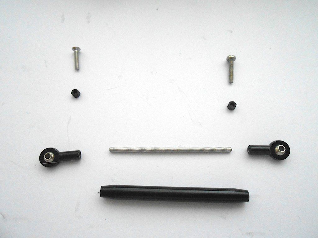 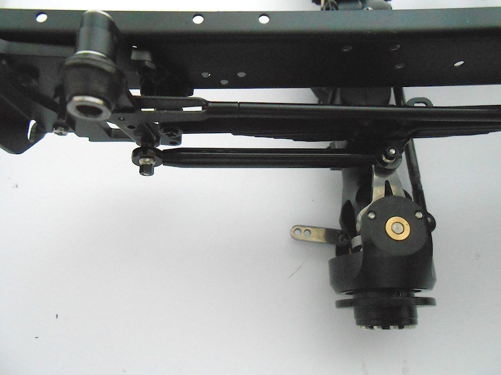 That's the first one done. Second one below. |
|
#44
|
||||
|
||||
|
The second axle is the same. Here I filed the little screw on top down to about 3mm. Because this is the throughput axle I was a bit concerned that at 5mm the end of the screw might interfere with the workings. On this one the track rod goes on the bottom.
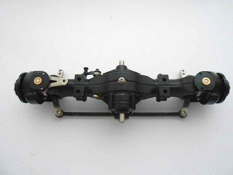 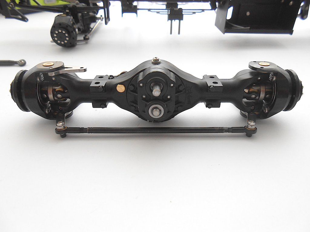 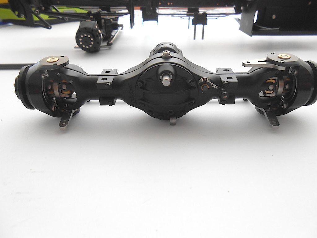 And here installed. For some reason this one put up a struggle and was a real pain to get on the suspension. I think one of the long screws was at a slight angle. 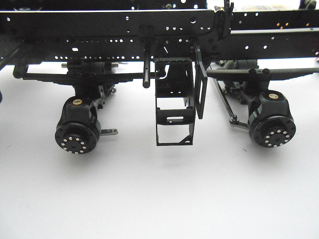 Connect the 2nd steering lever. Made sure both rods front and back were the same length. Here one of those little bolts fell out. Was thinner than the others. Put it back in with some Loctite. (One package of them had 21 and the other 22 so if one goes missing there are some spares) 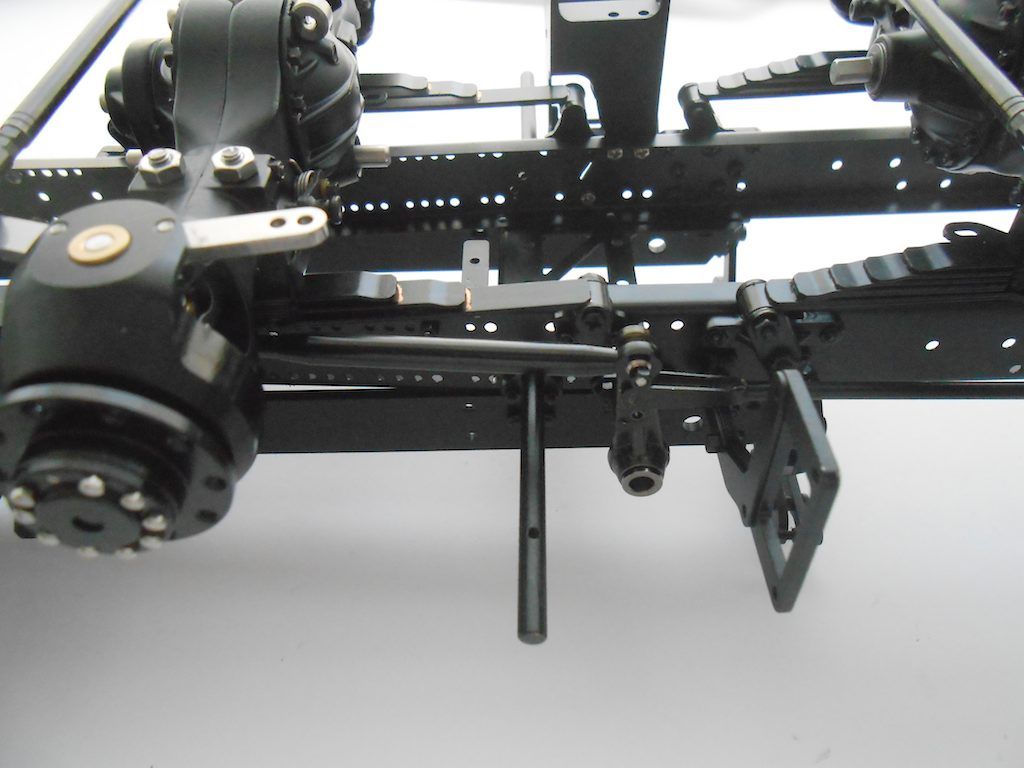 Here an overview. Added some lines. Looks like the front track rod needs some adjusting. 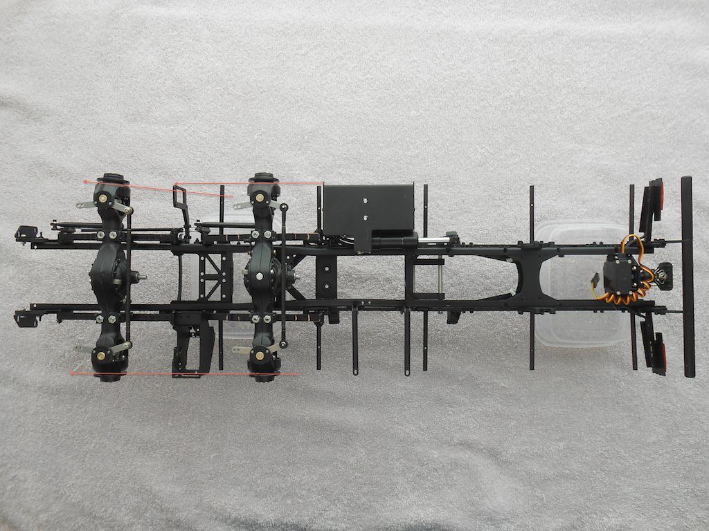 Best regards etc. Stephan Last edited by Rakthi; 05-26-2015 at 05:52 AM. |
|
#45
|
||||
|
||||
|
Just awesome. Everything about this kit is super cool.
|
|
#46
|
|||
|
|||
|
what a work of art, scale-art standard seems so much better than everything else in this hobby.I got a scania 143 streamline, made from brass, from when scale-art was Brand modellbau, even back then the quality was top notch, can't wait to see your build finished, keep up the good work.
__________________
René ____________________________________________ To view links or images in signatures your post count must be 10 or greater. You currently have 0 posts. To view links or images in signatures your post count must be 10 or greater. You currently have 0 posts. To view links or images in signatures your post count must be 10 or greater. You currently have 0 posts. ____________________________________________ |
|
#47
|
||||
|
||||
|
Yes, Prop, Roundabout, the parts of this kit are really something else. Pictures just don't do it for the detail and care with which they were made. They also keep updating and improving the parts, even on this kit. It is expensive stuff, but it sure is top of the line as far as building kits is concerned. Having a brass one must be interesting! There still is a section called "Brand Modelbau" in their shop. Mostly small detail stuff for US trucks.
Well was set to post the rear axles stuff, but we are having a tropical downpour here and internet is slow as a poke. Will see if I can get the pics uploaded. |
|
#48
|
||||
|
||||
|
Rear axles .. here a picture of all the parts. (forgot the leaf spring bits)
The bits in the "ScaleART" plastic were in the boxes with the axles. The other parts were in the "rear suspension" package. 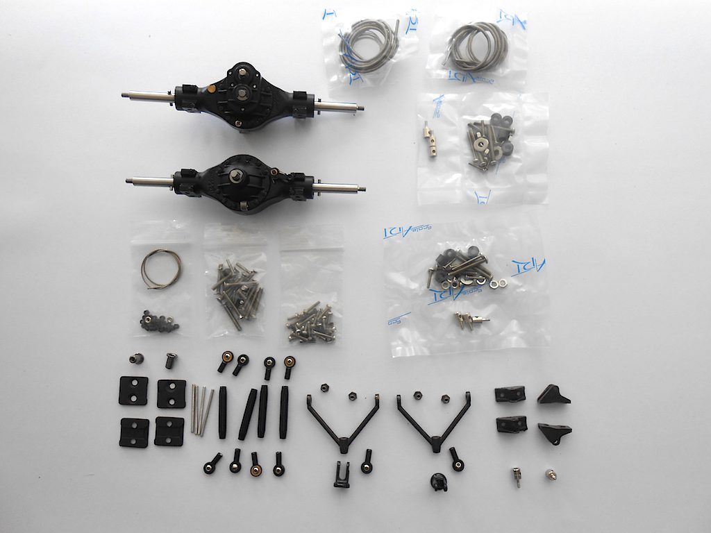 Note: this whole assembly was done with the frame upside down - just to make it more interesting. First we assemble both triangular parts. Turns out the everything (marked with arrow) is threaded. So a bit of thought has to go in the assembling. 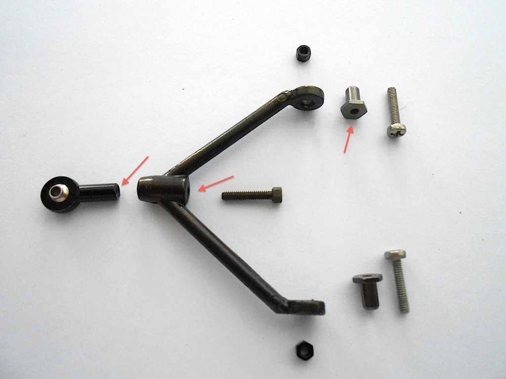 After giving it a couple of trail fittings in the chassis, found out it was not going to be that easy. The triangles have to be installed so they can still easily move up and down. It takes some fiddling to get it just so. A bit of grease where the bushing is going is a great help. Before the bushing, screw and nut would move together. After applying the grease, at least the bushing, screw and nut didn't budge when moving the triangle. 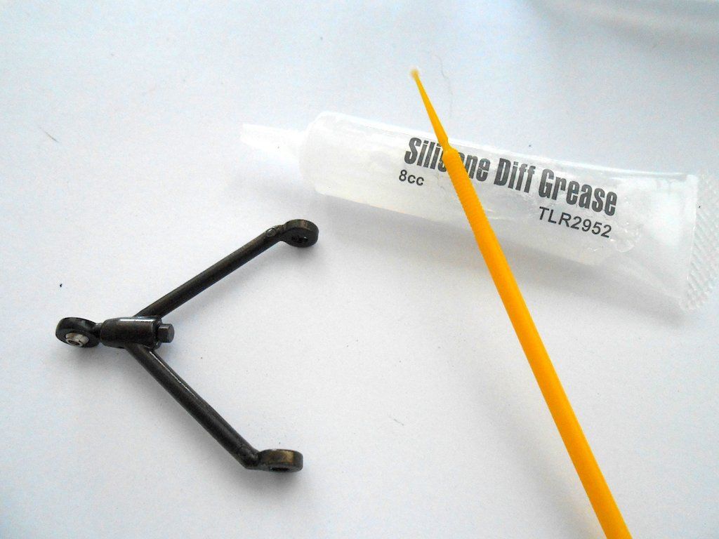 Here they are installed. (Loctite applied to about everything) 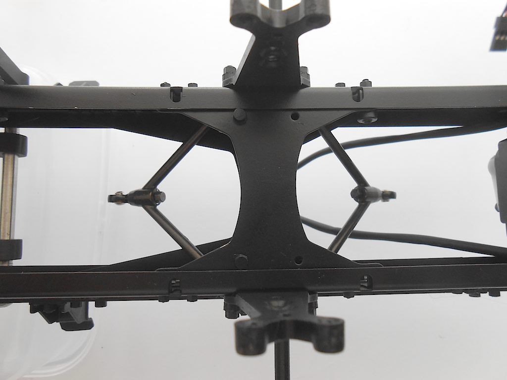 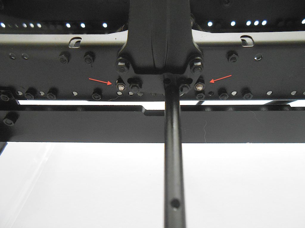 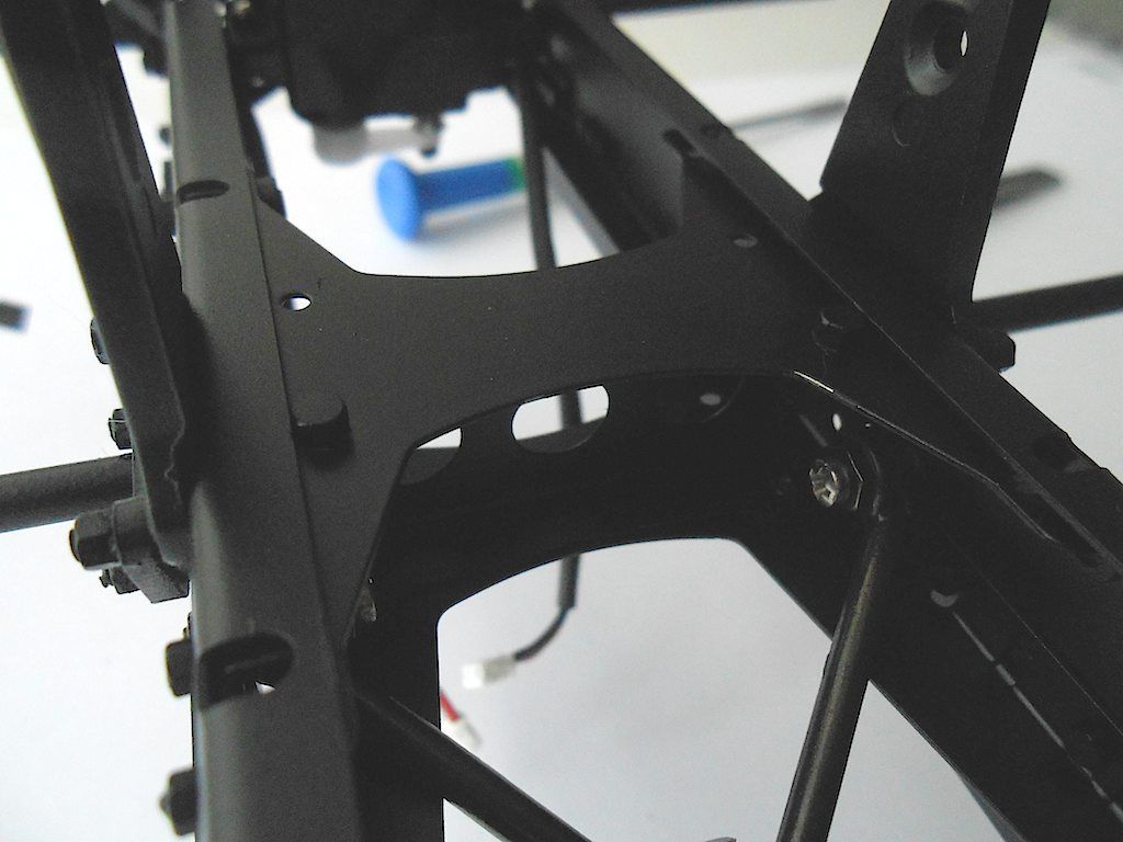 Next the leaf spring packages. I replaced the silver phillips screws with hex head ones I had lying around from the Capo. (easier to install with a ball head driver than a philips screwdriver) Apply grease to the inside of the hole where the bushing goes and attach to the lower of the 2 holes (or higher when working upside down). Loctite applied to the inside of the threaded bushing. 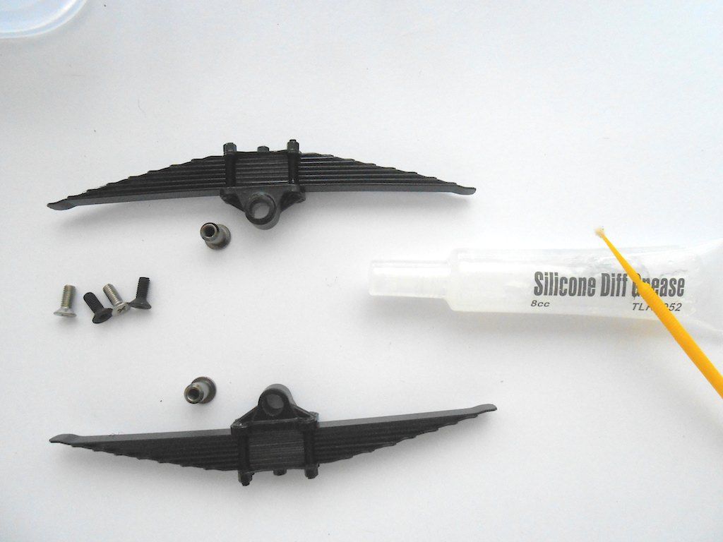 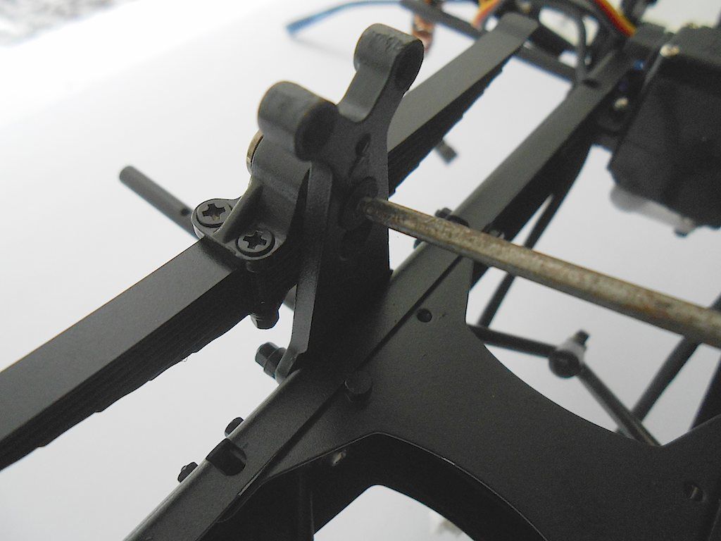 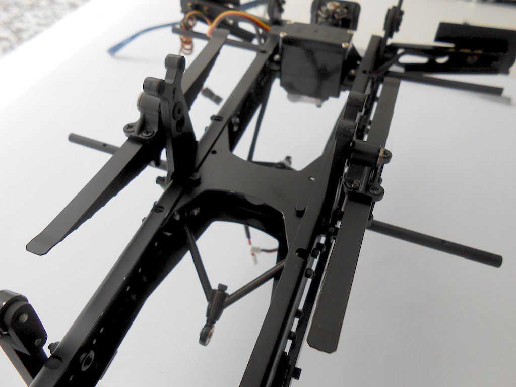 Next prepping the actual rear axles for installation. 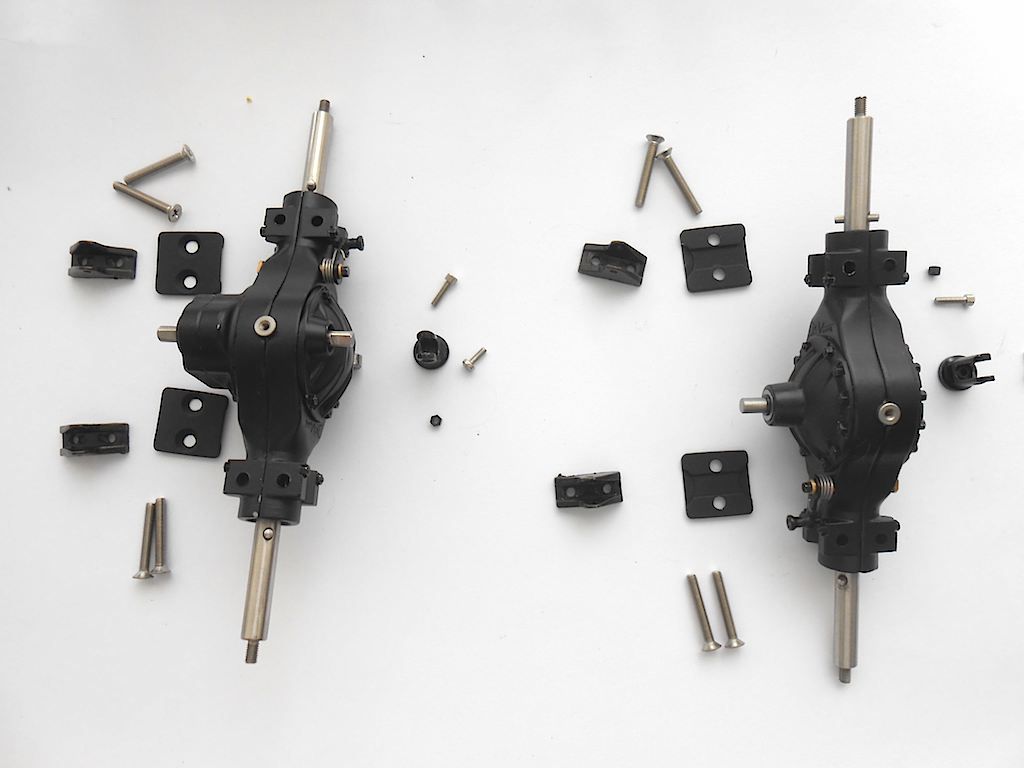 First connect the bit that will attach the axle to the triangle. This part has a cut out in the centre that fits over the stainless steel part and the bottom is also slightly rounded so it sits perfectly on the axle casing. On top, one of the holes is threaded, the other is not. So 2 little nuts I thought I would need are extras. It is also a good idea to first test the fit of this little piece on the triangle (how do I know?) ... One of them needed a bit of widening before it fit. 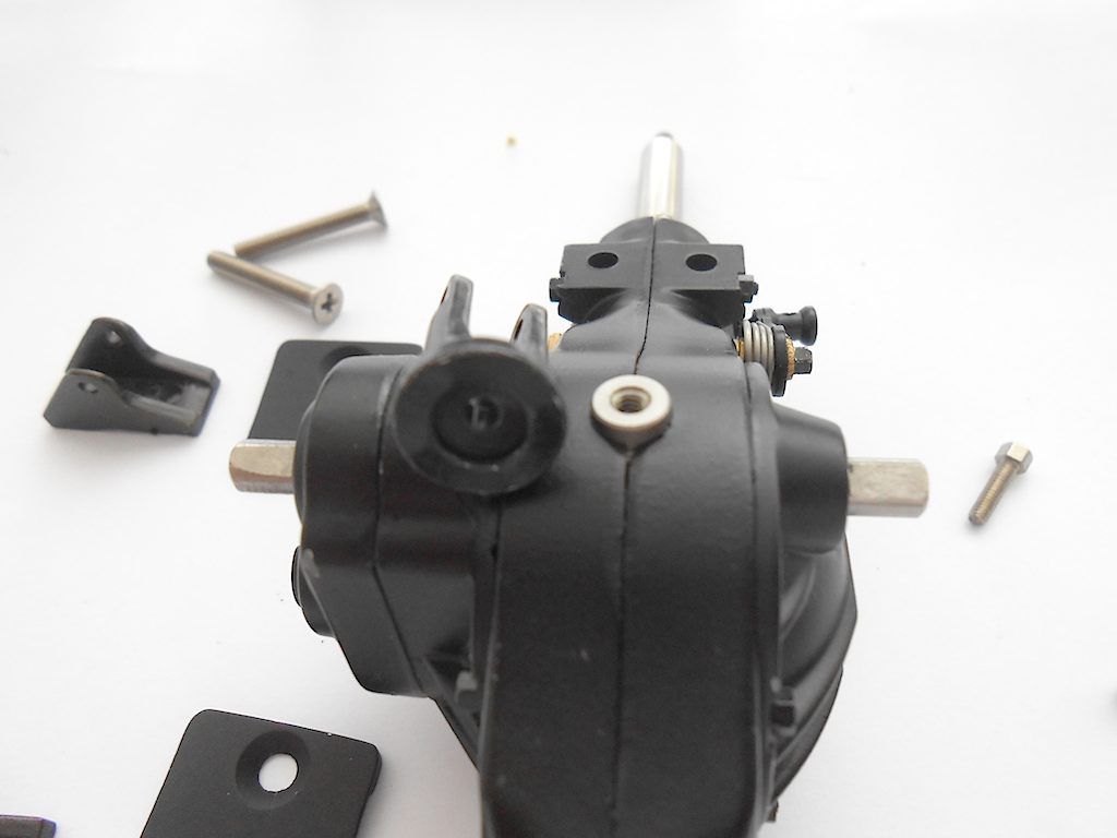 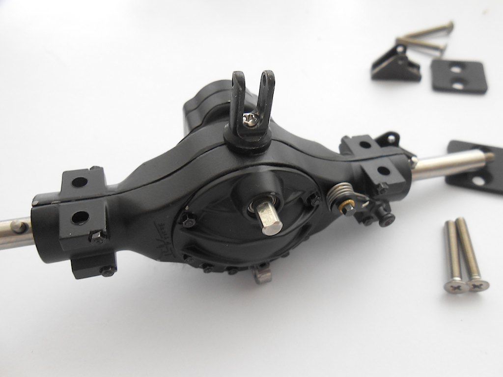 axle ready to install 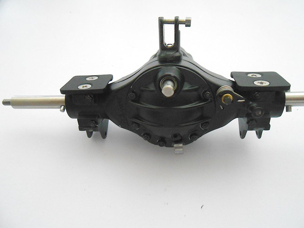 Rear axle attached to the triangle 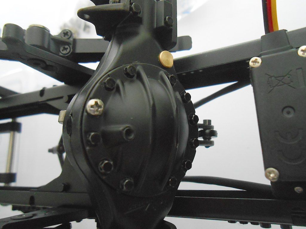 Both installed and balancing on the leaf springs. (connecting the axles to the triangles is another one of those moments that invites the use of colourful language  ) )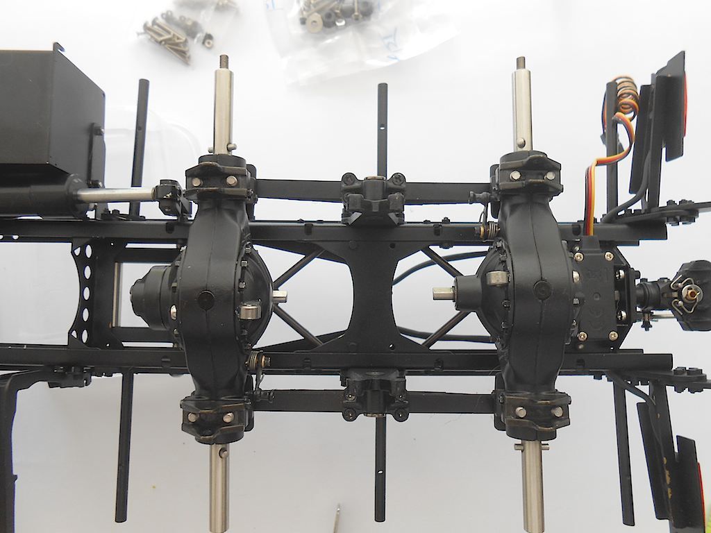 Next we need the 4 track rods. Manual states to set them at 50mm and if needed do adjustments later once wheels and fenders are installed. 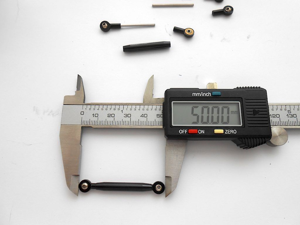 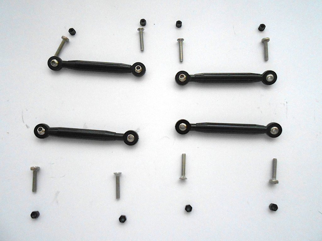 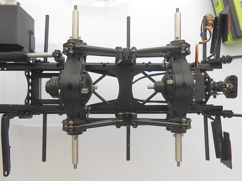 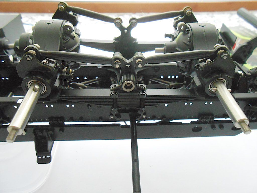 View right side up 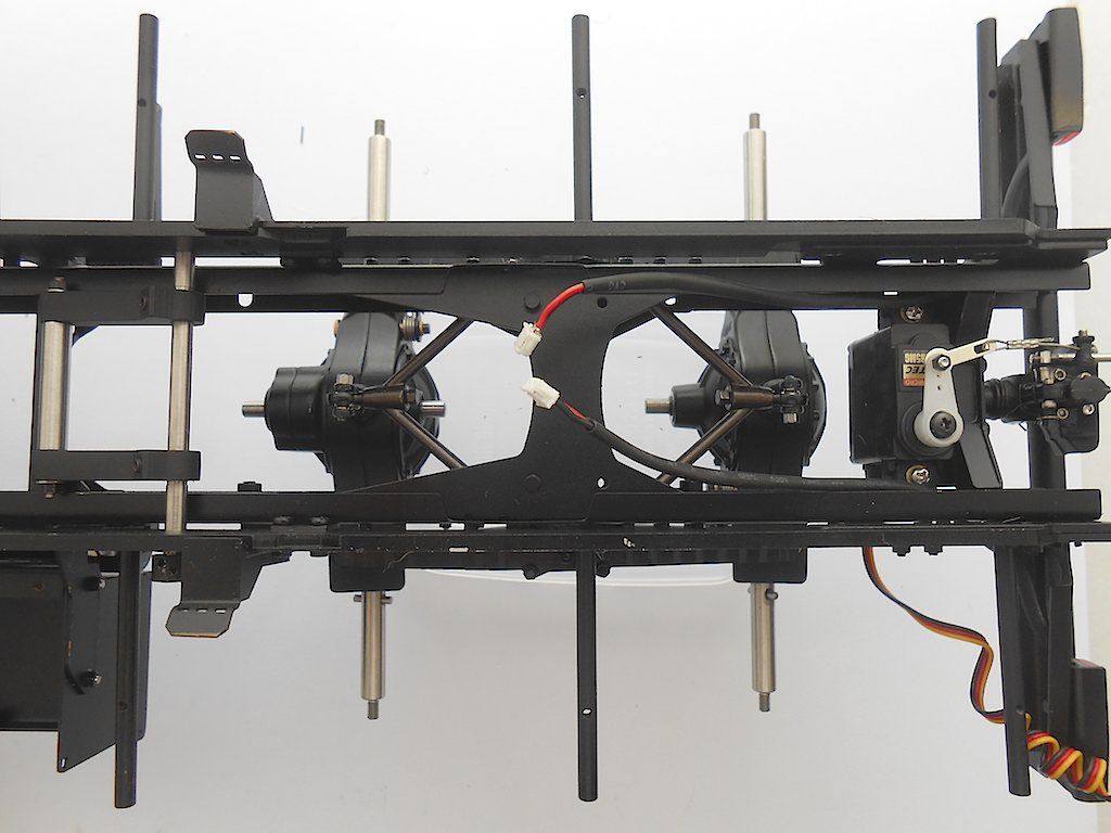 Whole frame from above 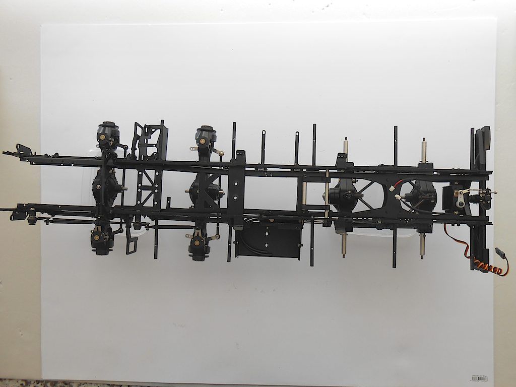 and upside down 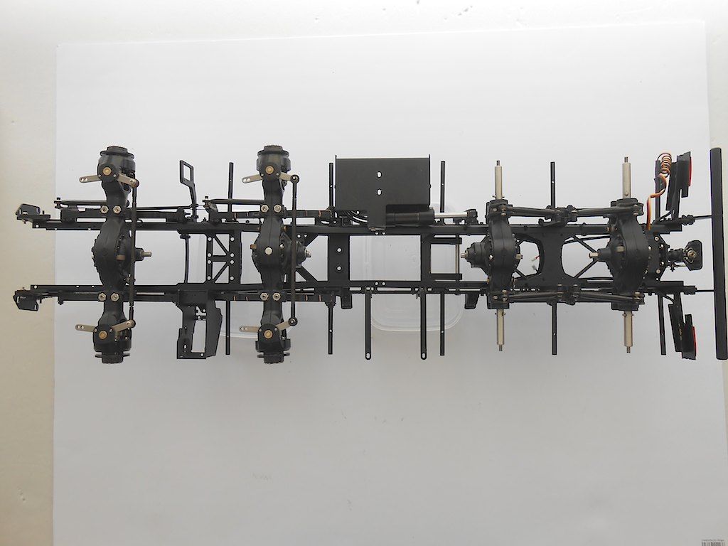 And as point of interest ... these are the bits left over from the packages supplied. Never even opened those that came with the axles. 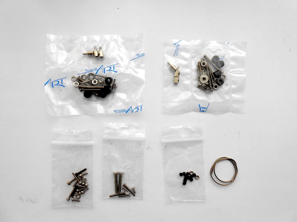 Next supposed to do the servos for the diff lock and the bowden cables, but might put that of for a bit. Probably will assemble the wheels and fenders next. Just to get the thing on wheels. |
|
#49
|
||||
|
||||
|
Quote:
Just gorgeous stuff! |
|
#50
|
|||
|
|||
|
Simply a masterpiece...
|
|
#51
|
||||
|
||||
|
Prop, Louisbaby ... yup those guys at ScaleART know what they are doing.
Stephan |
|
#52
|
||||
|
||||
|
Started assembling the wheels. The front ones just bolt on, the rear ones need to be bolted together.
The front gets a wide tire. The rear 2 thinner ones each side. 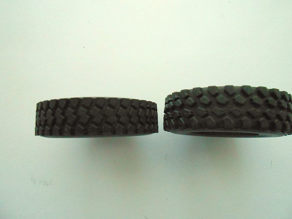 Didn't get around to putting them on the axles. So only the rear ones. 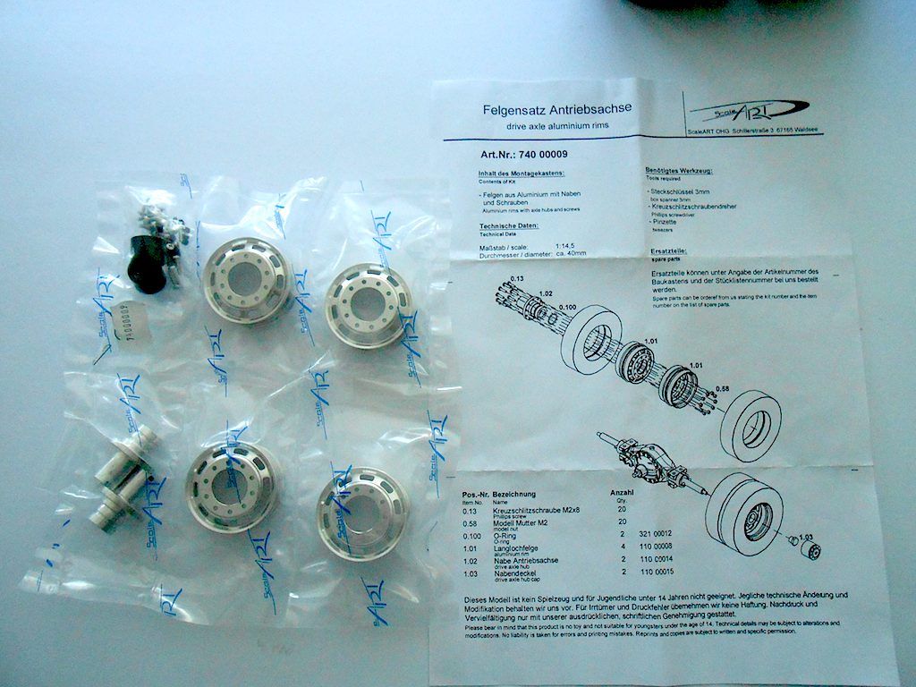 The little rubber bit is to hold the black cap on. 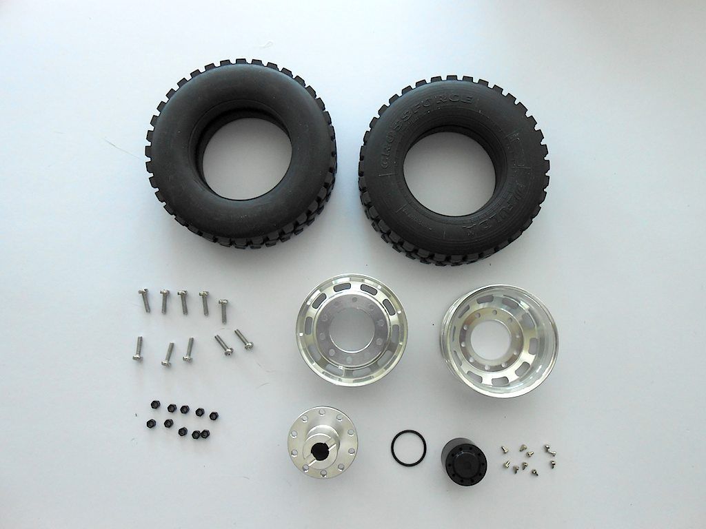 Here too we add the little decorative bolts. No need to drill the holes out, most of the little bolts just slide in. So some Loctite applied to the holes. 3 of them "escaped" not to be found when doing the 4 caps. Good thing they provide some extras. 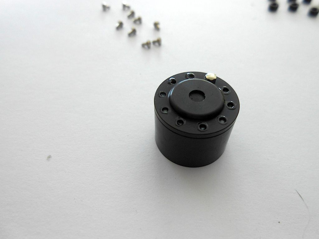 Only 3 of the 40 installed needed a tap with the hammer 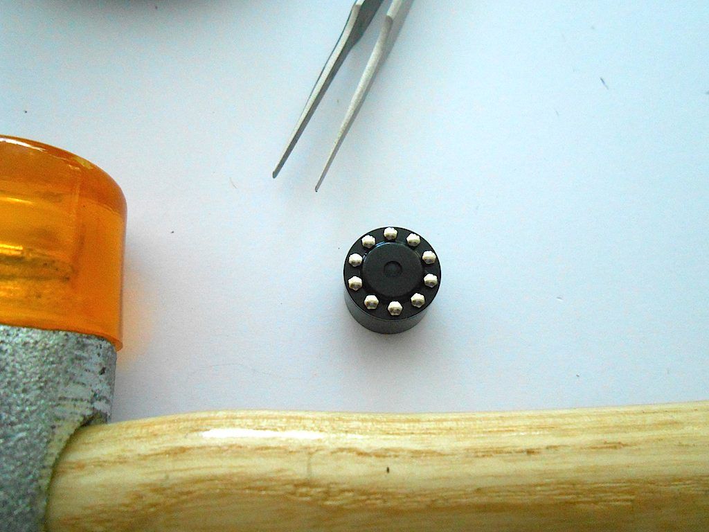 First install the rubber ring on the centre piece. Would be a pain afterwards. 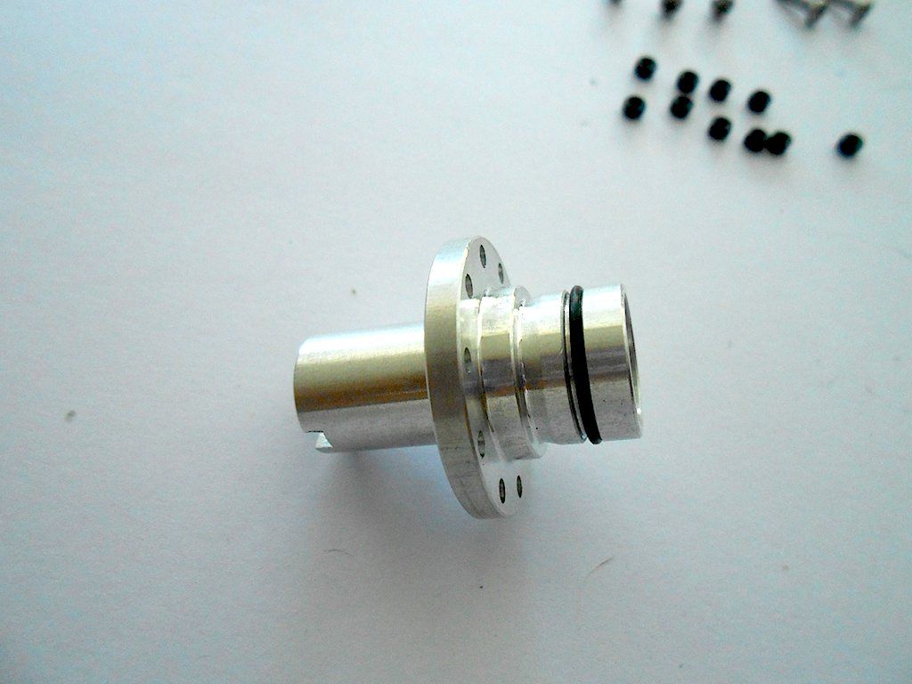 Then simply slide the 3 parts together and fasten them 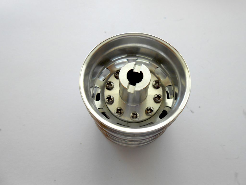 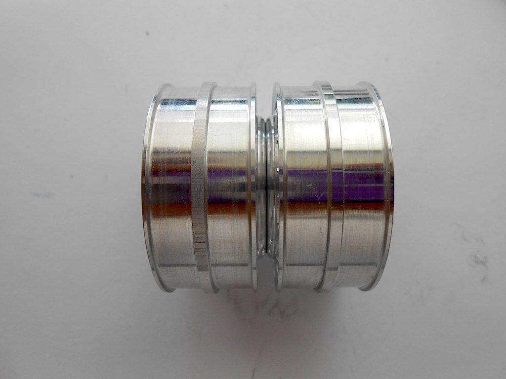 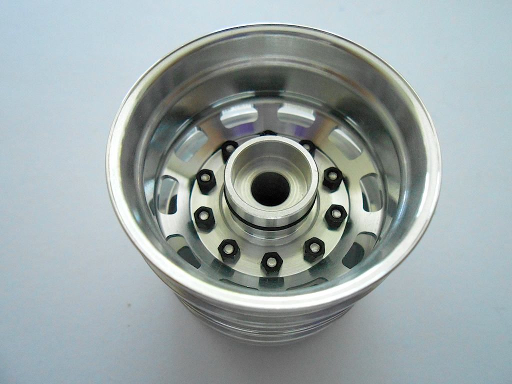 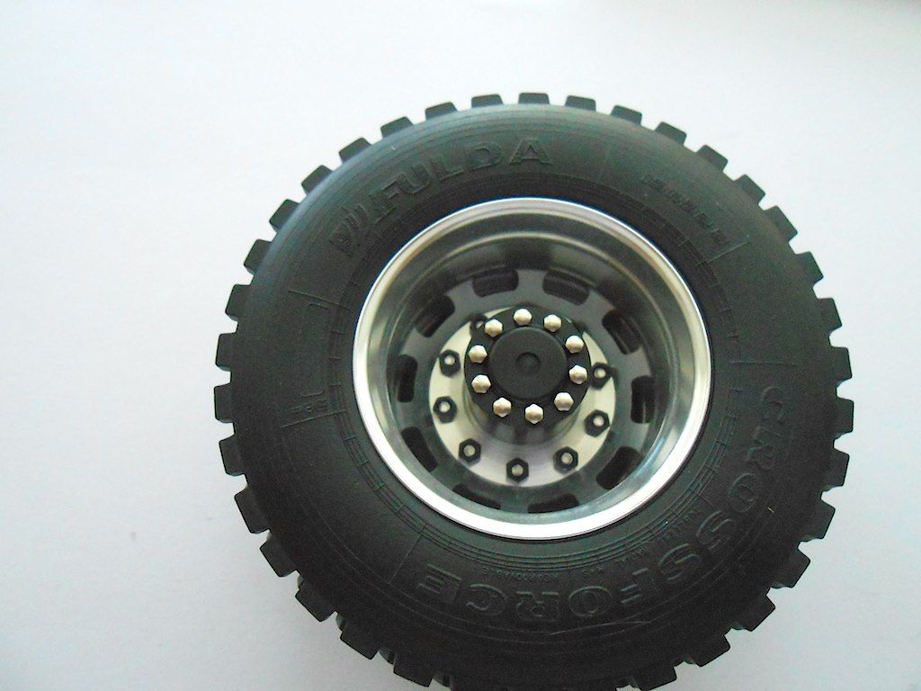 Instead of bolting them to the axles, decided to do the diff lock servos. This turned out a real pain. First prepping the servo horn and add the bowden cable holder. (Holder needs to be installed so it can still move a bit) 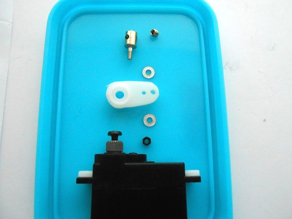 Servos and other bits ready to be installed. (each servo is for 2 axles) 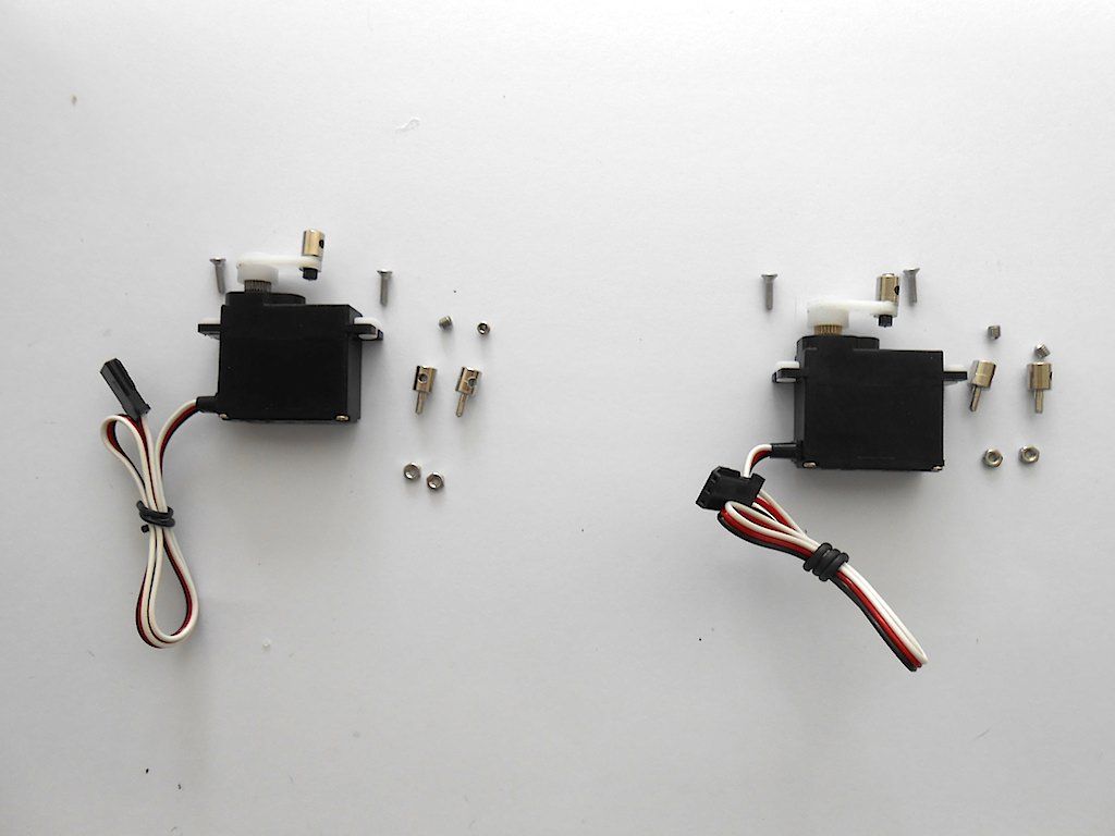 These were a pain should have installed them earlier. 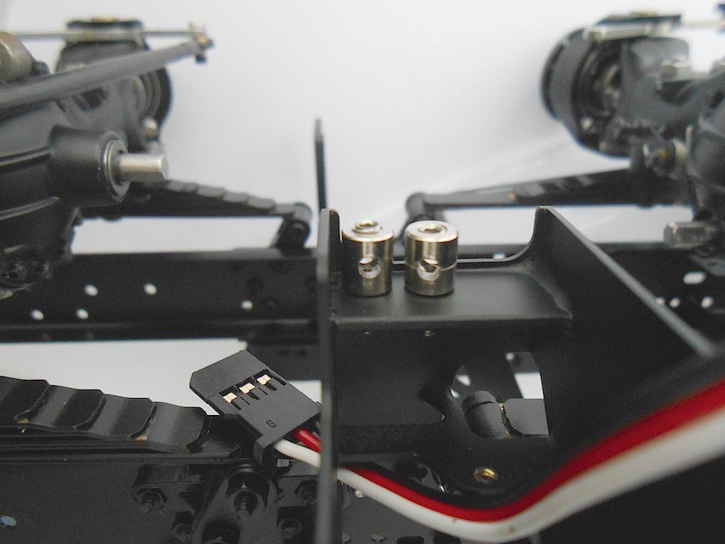 Luckily access from underside. however none of my wrenches fitted through. Ended up holding the nut in place with a pair off strong tweezers and screwing a long M3 bolt where the grub screw goes. Then tightened up by using the M3 bolt. 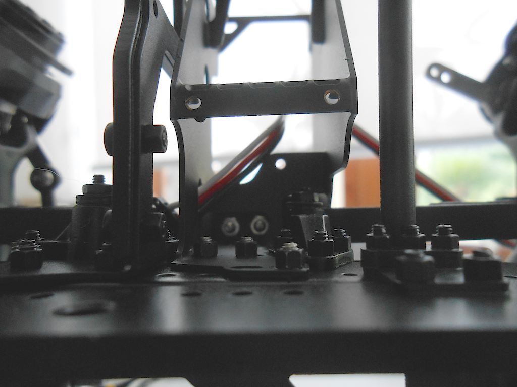 Front axles servo installed - horn in the diff closed position. 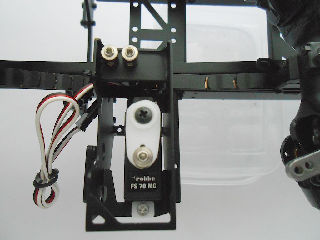 The one for the rear axles should have been installed before the axles. Almost no access to the screws. The 2 bowden holders were a struggle too. This one too in the diff locked position. Unlocked will be 90° turn towards the leaf springs. 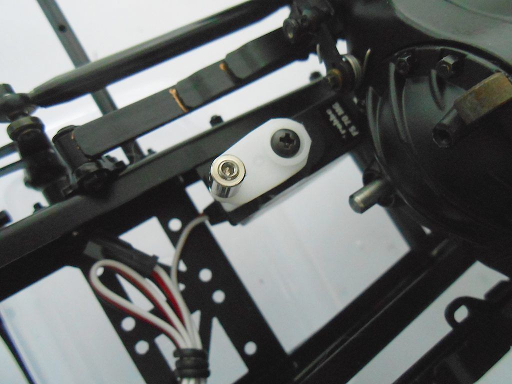 Almost had to remove the axle to get to the screw that holds the servo. 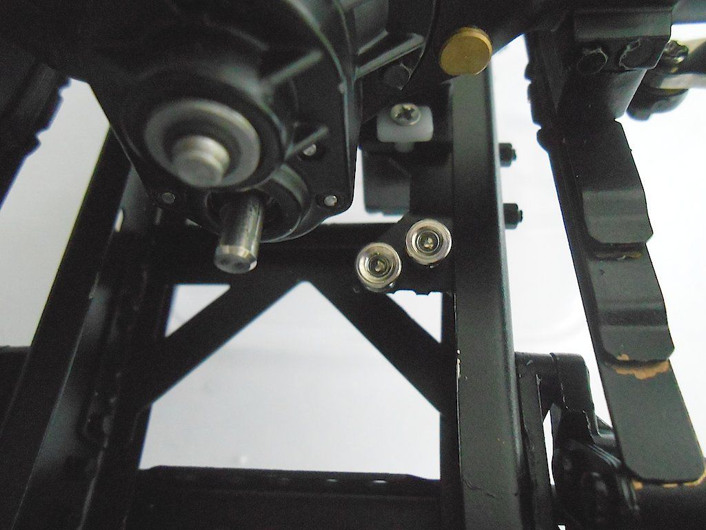 Have to remember to install the support bracket for plate that will hold the electronics before I get in a tight mess there too. Worn out ... Cheers! Stephan Last edited by Rakthi; 05-28-2015 at 05:18 AM. |
|
#53
|
||||
|
||||
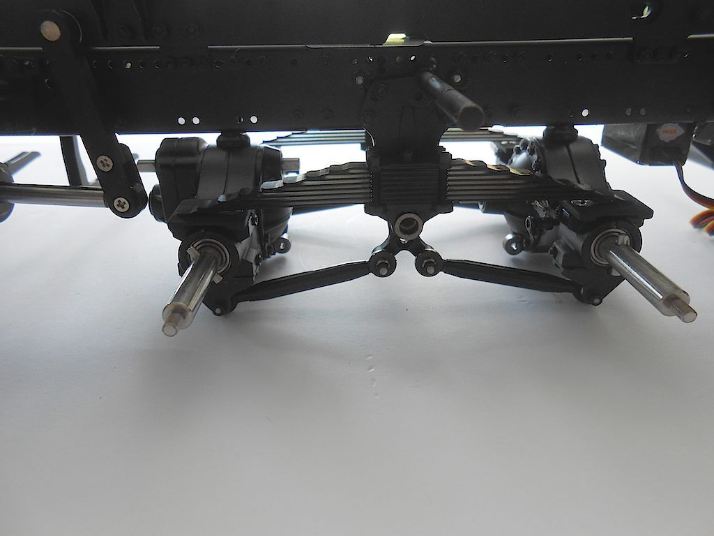 Since I reminded myself, I installed the supports for the electronic platform This need be done now. Once the drive train is in, no more access to that area. 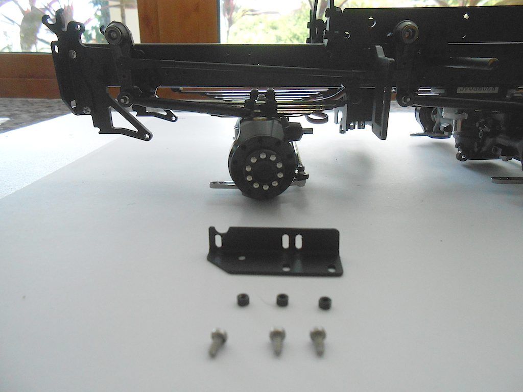 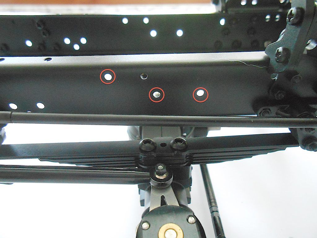 A bit tight to install because of the steering rod. Another area that will need some touch up later on. 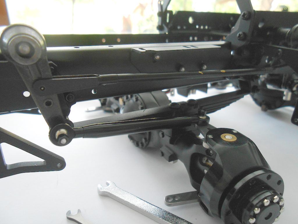 Other side was easy 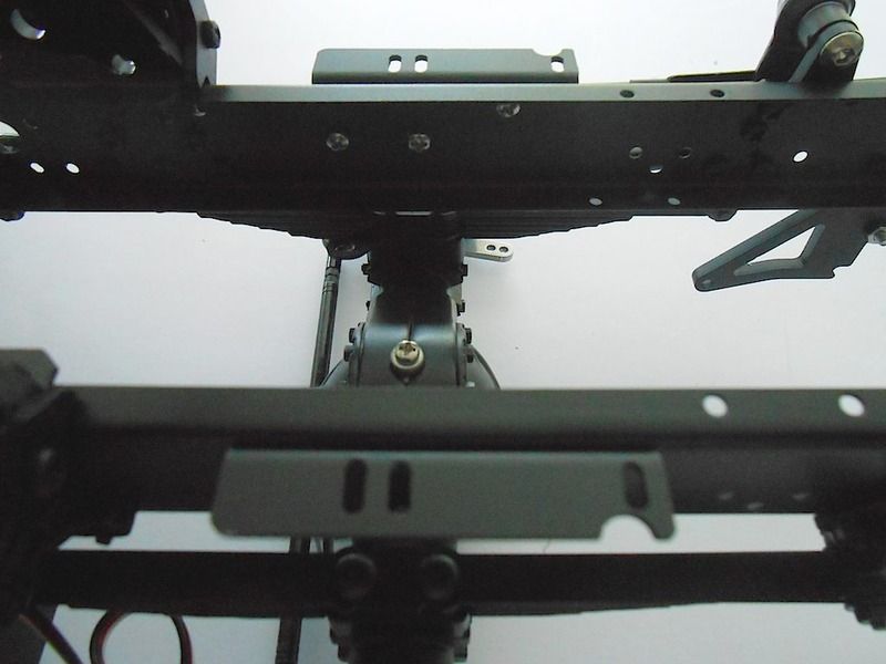 Next up the cover of the diff lock servo of the front axles. 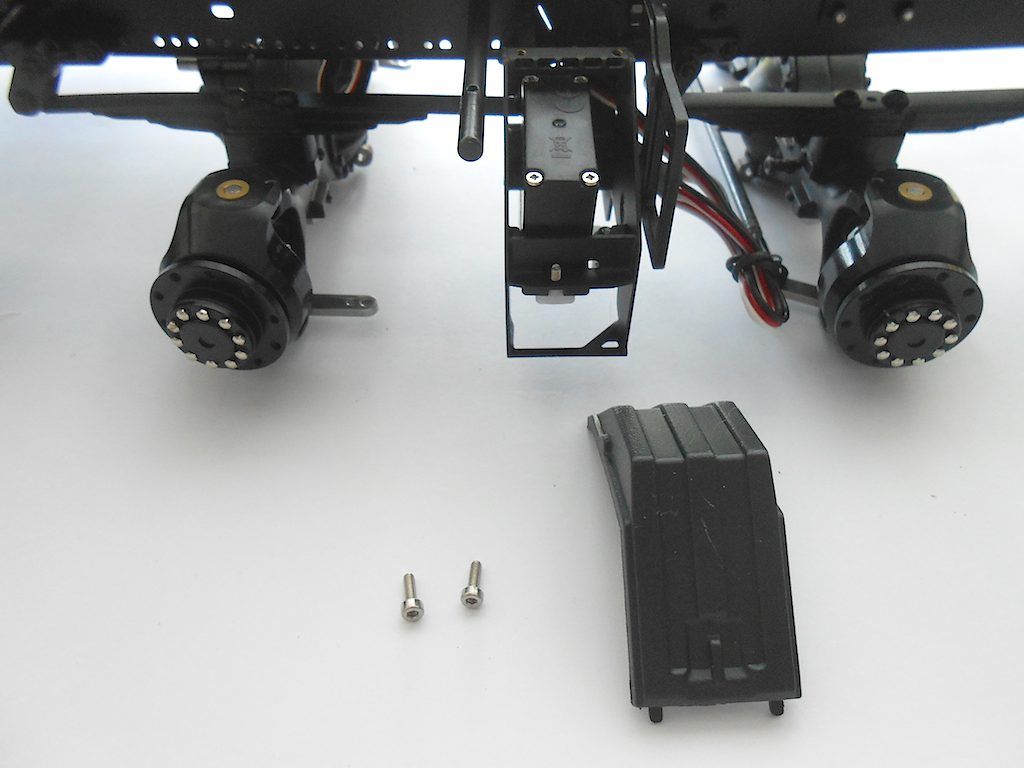 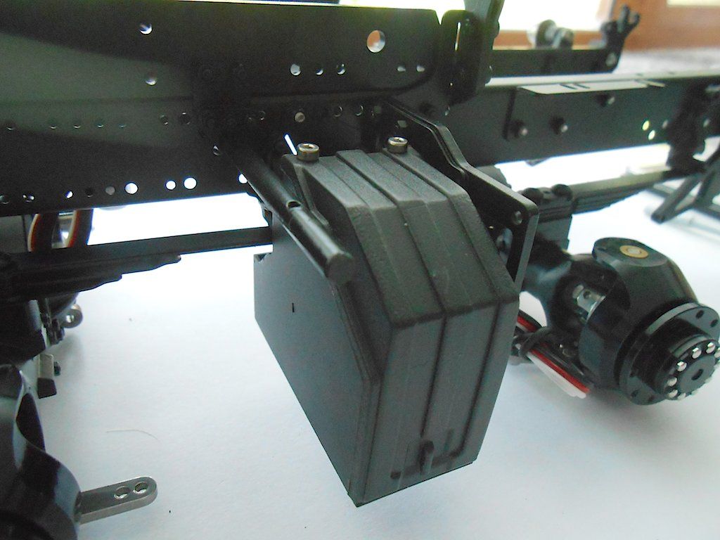 A nice detail, there is a slot just slightly bigger than the plug of a servo so you can stick the wire through. 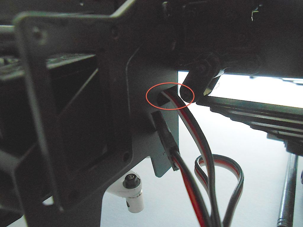 Next front wheels 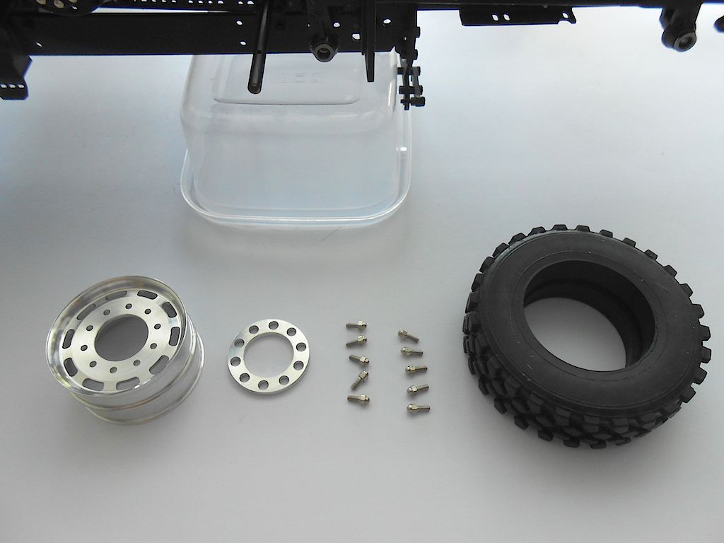 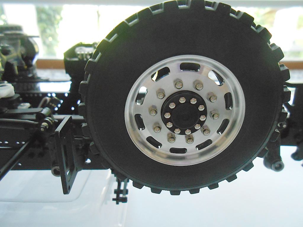 The protection ring just sticks on. This one clamped in place by itself, but the 3 other ones will need a bit of hot glue or some other sticky stuff if I don't want to loose them first time around. 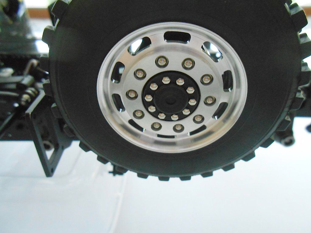 Rear wheels. The washer and nut are the only thing I used from the package of fasteners that came with the rear axles 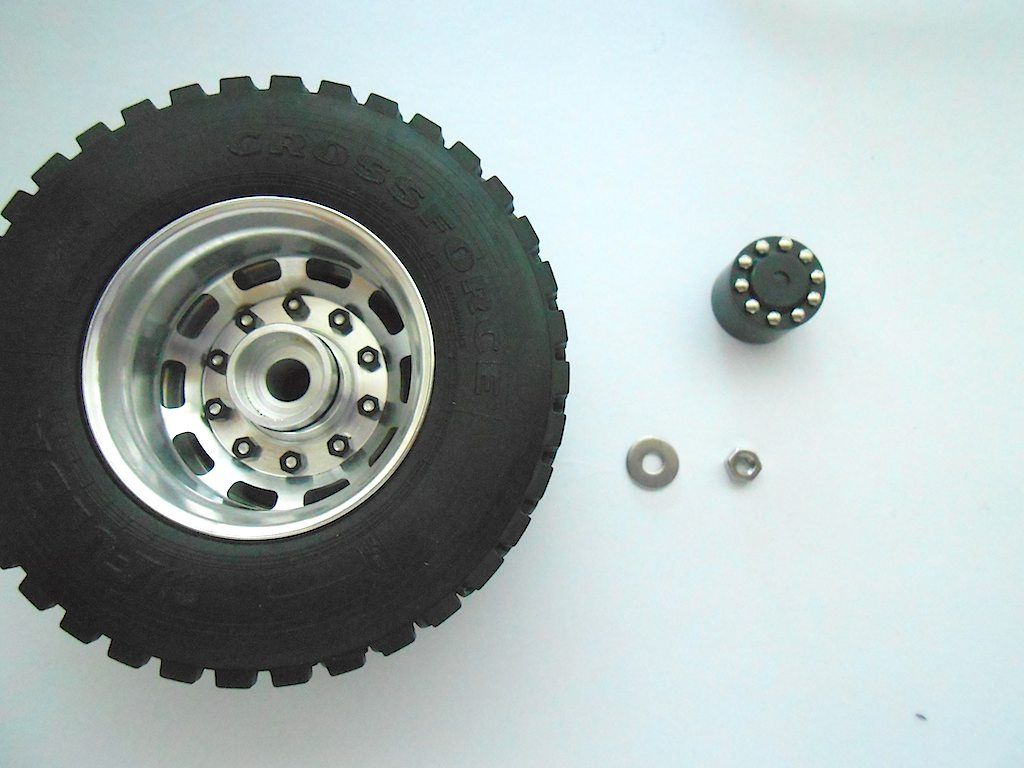 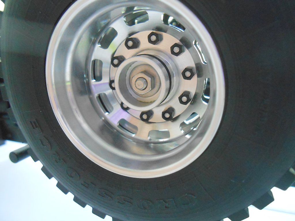 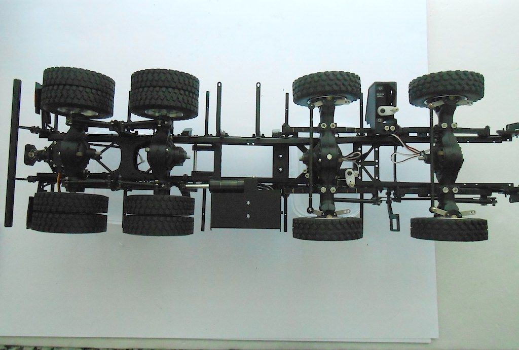 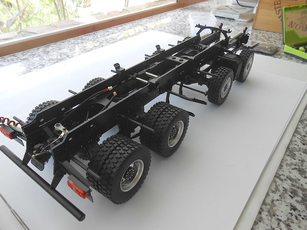 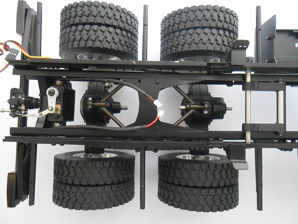 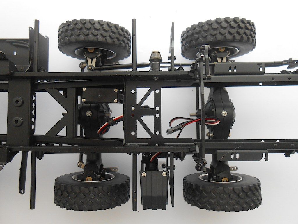 Next up is supposed to be the motor, gearbox, transfer box and prop shafts. 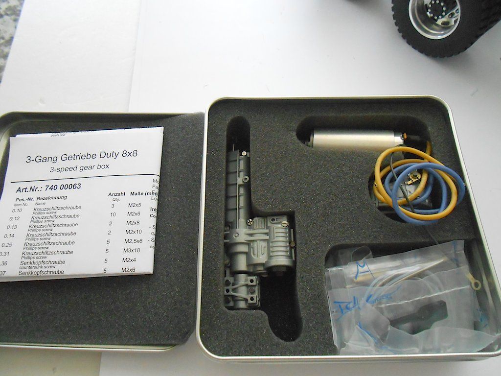 But, waiting for exhaust pipe that needs to go on before all the above goes in. Want to wait with the bowden cables to, to see how they work with the motor etc. Guess I'll just read through the book and see what I can do in the mean while. |
|
#54
|
||||
|
||||
|
Cant wait to see the engina and trans on this thing!
|
|
#55
|
||||
|
||||
|
I'll post some pics of it tomorrow. Once it's in the truck it is barely visible. Not as impressive as the one on your Jeep though. Ready assembled and greased too, just like the axles.
Think I take a break for a couple of days, back hurting from hovering over the model trying to get a handle on those nuts and bolts. And actually should finish varnishing the front door ... for some reason I haven't have found the time for that  Stephan |
|
#56
|
||||
|
||||
|
Hi Prop, here the promised pictures. It's a 3 gear box and a transfer case. In normal operation, the power of the motor will go only to the rear wheels, when you lock the transfer case you are in 8x8.
Nicely detailed and beautifully fitted. Once installed you can only see it when you turn the truck on it's back. The electrical motor is a brushed one. It's a Faulhaber 2657, 46Watt one. Screws into the gearbox and immobilised with a grub screw. The transfer case threw me a bit, it gets placed in the middle, so the input and output size go towards the front. The position of the locking bit was confusing until I realised you are supposed to run the cable through the provided hole (you can see it on the left in the 2nd picture) and then with a 180° turn towards the front of the frame. (I guess this is also why this is the only one where the bowden cable has a teflon insert. 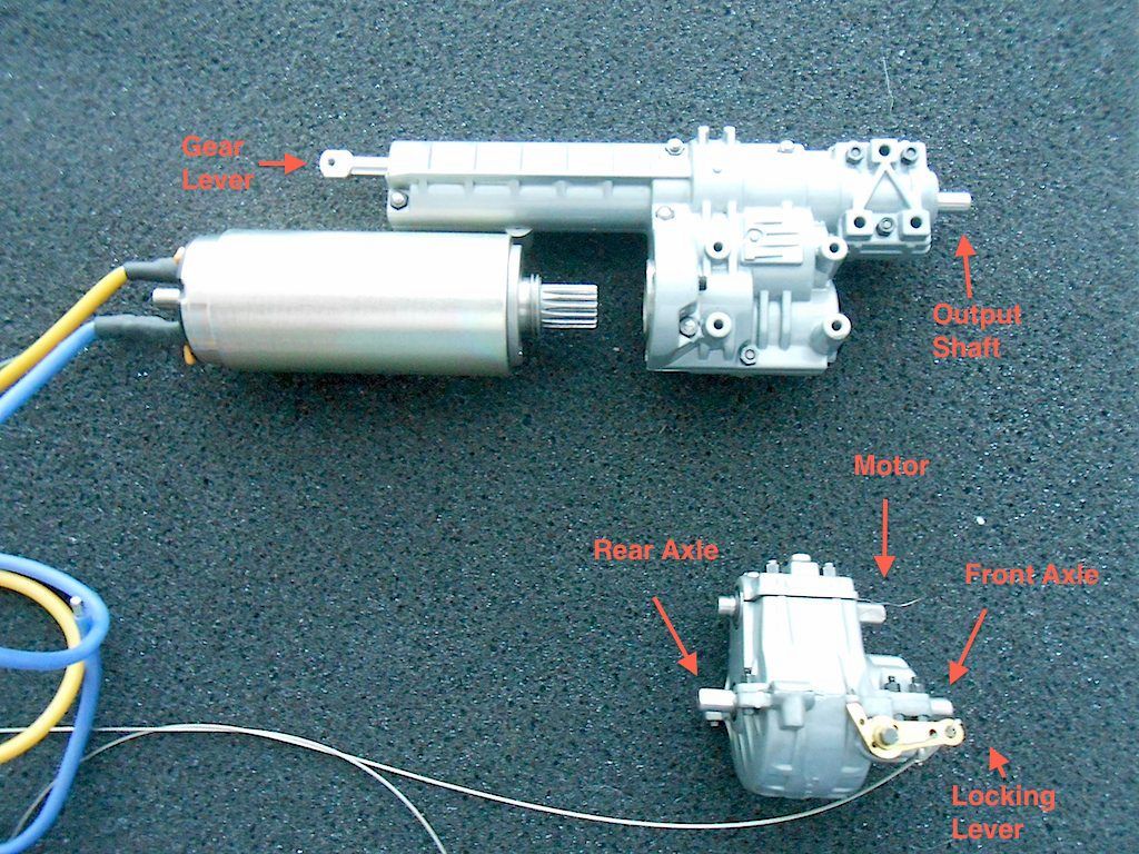 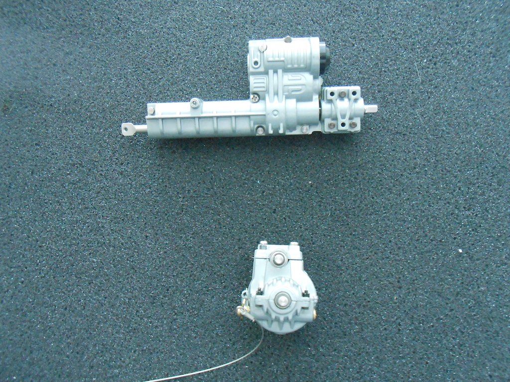 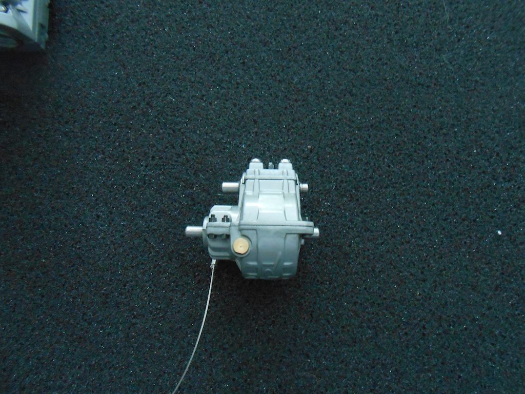 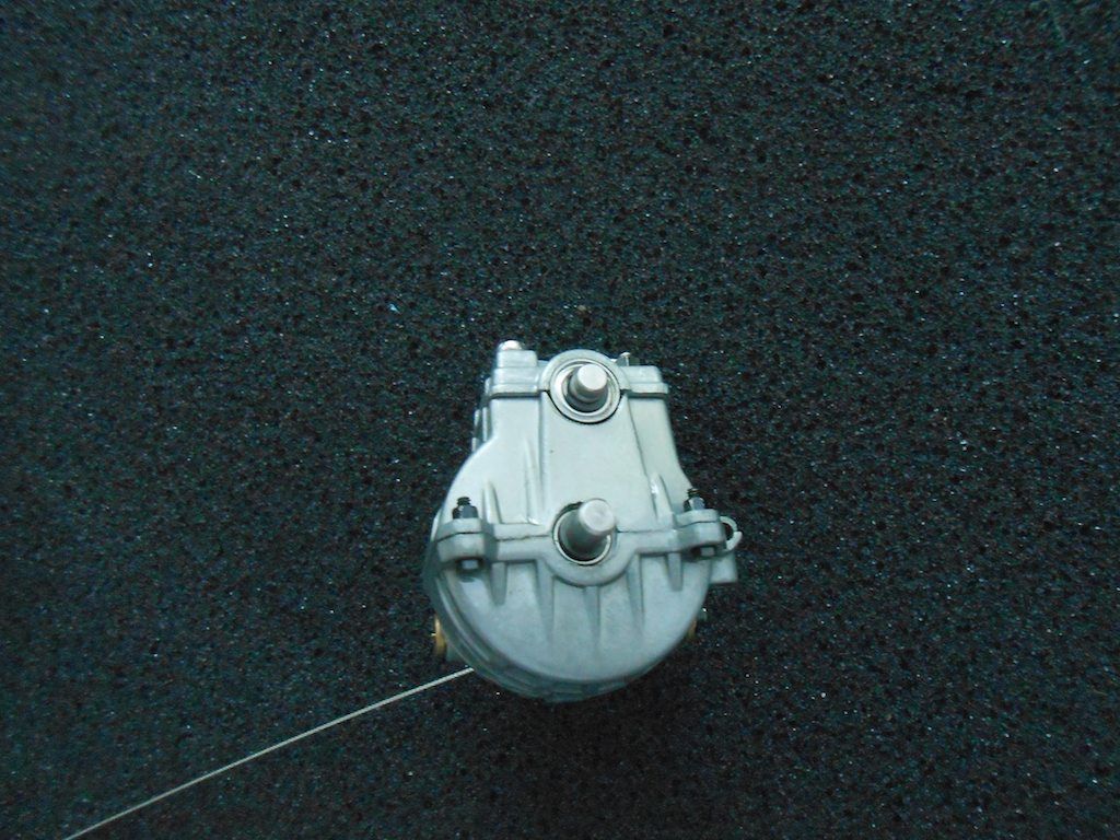 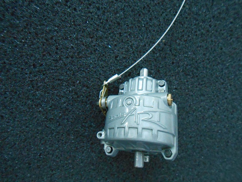 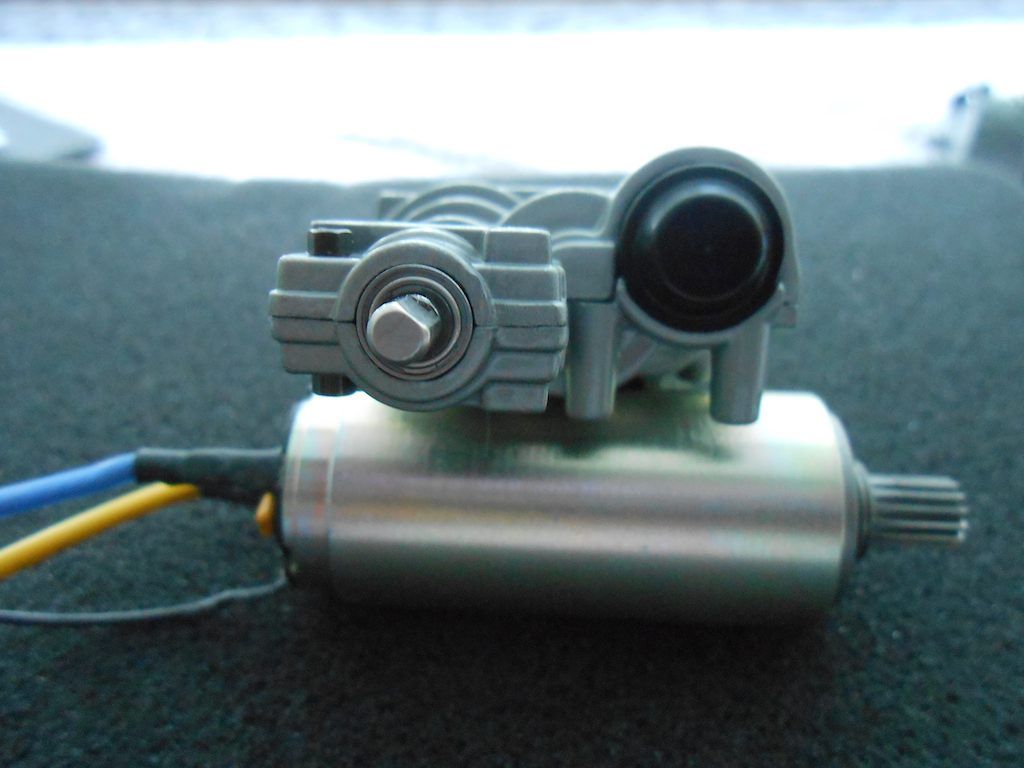 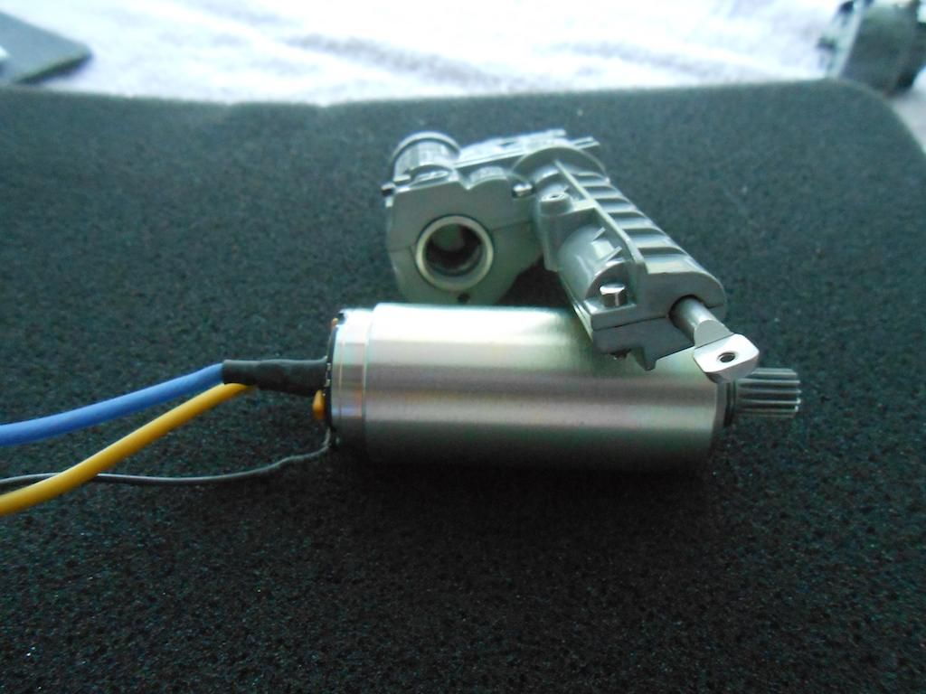 Propshafts. Top one is from motor to transfer case 2nd one is between 2 front axles 3rd and 4th one is either between the rear axles or from rear axle to transfer. (can only see once transfer case is installed) Last one is from transfer case to the front axles. 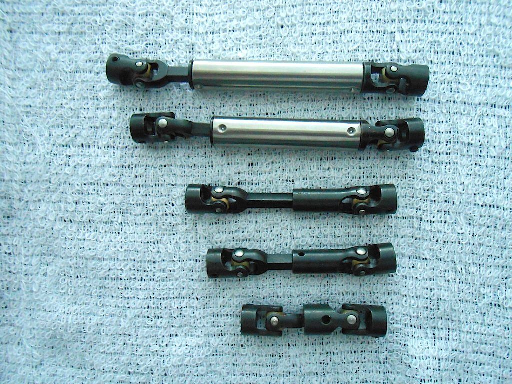 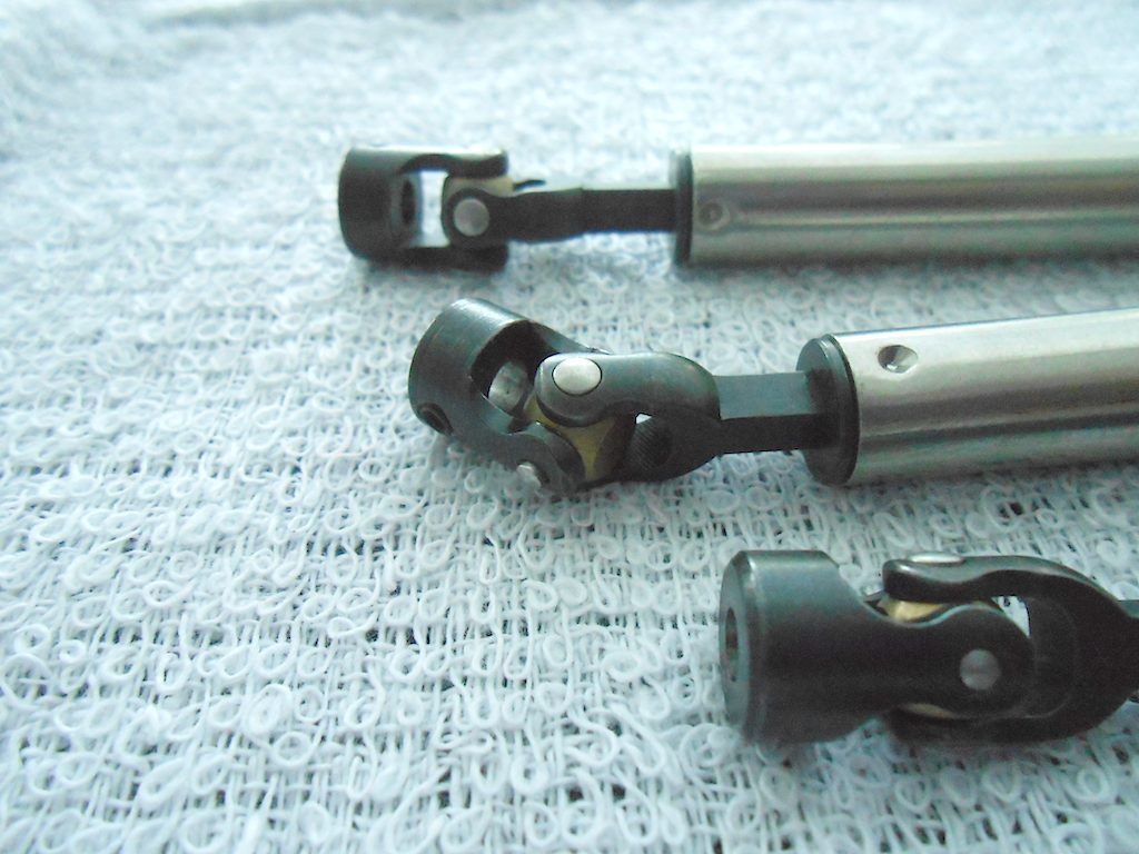
|
|
#57
|
||||
|
||||
|
Got around to assemble the rear part of the roll on roll off mechanism.
Here all the bits and pieces in the approximate place of assembly. 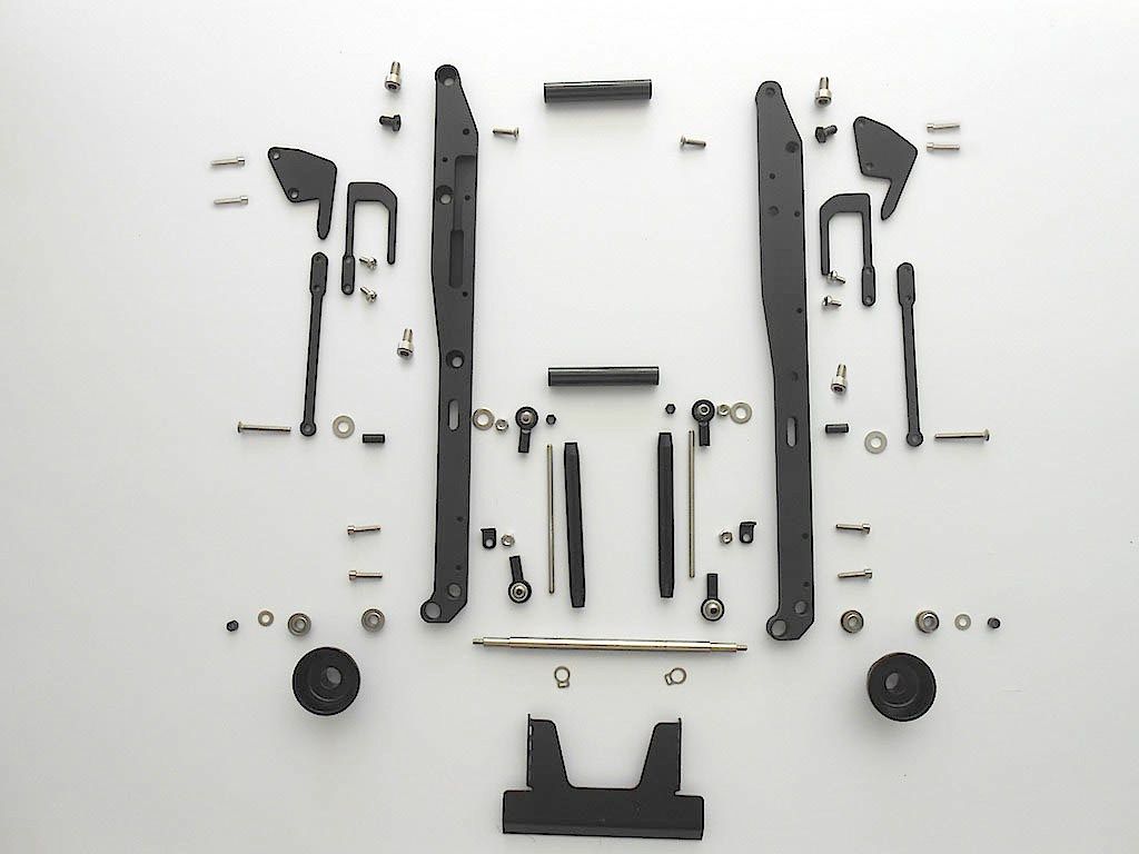 First the main frame assembled 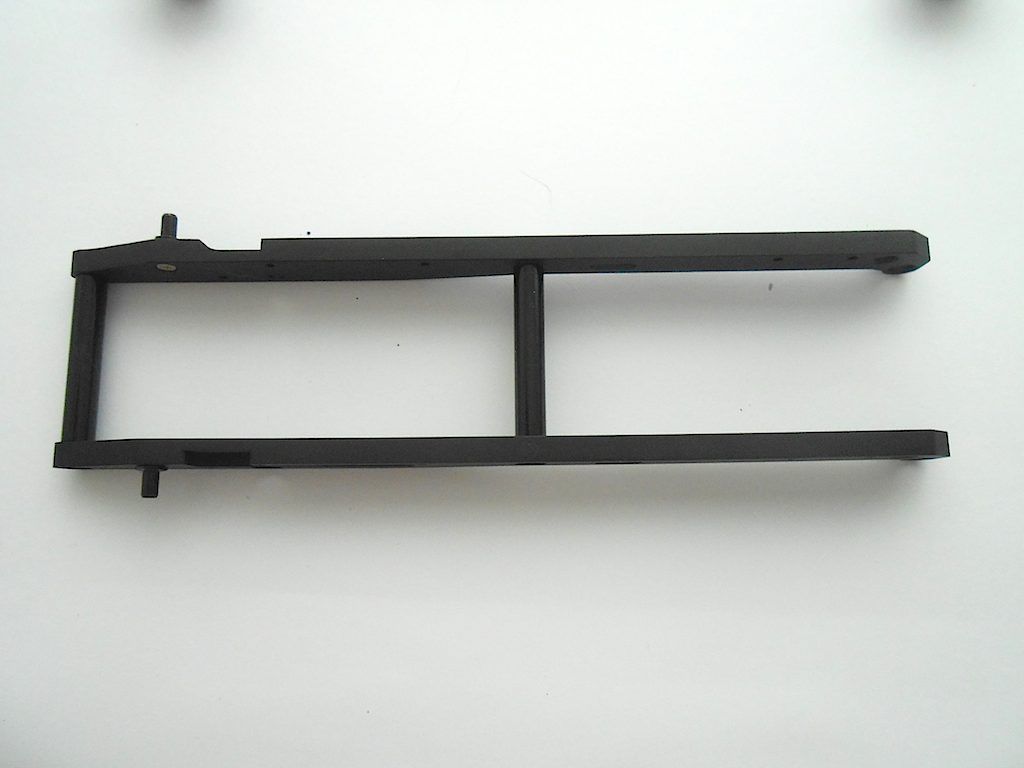 Then the sliding and fixed hook that hold the container in place. 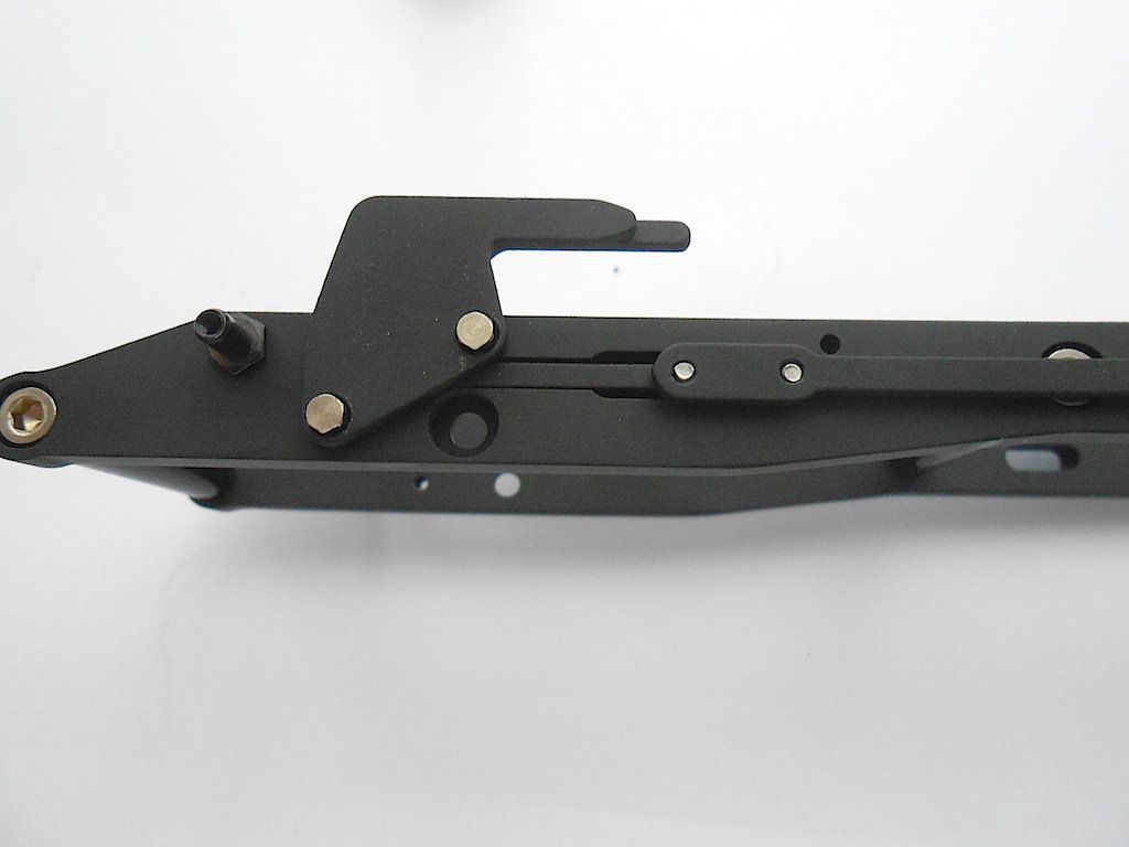 Ran into a problem with the right one. The frame is milled to create a channel in which the mechanism can slide back and forth. I guess the bit used in the milling was a bit worn or damaged and the machined surface was rough. Tried to flatten it with a small flat file. It worked up to a point. 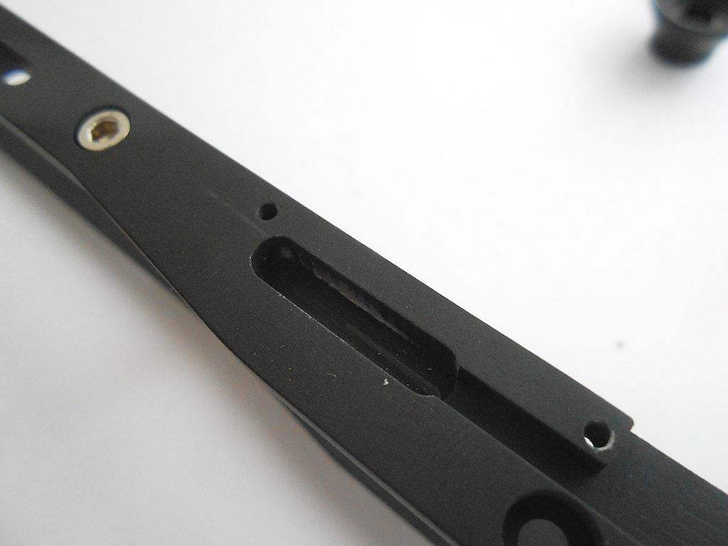 Then I realised that it was the screwheads that were getting caught in the rough area. So too the file to them and problem solved. At one point I used the dremel and accidentally filed a bit of the actual piece too. No biggie as it is not visible. 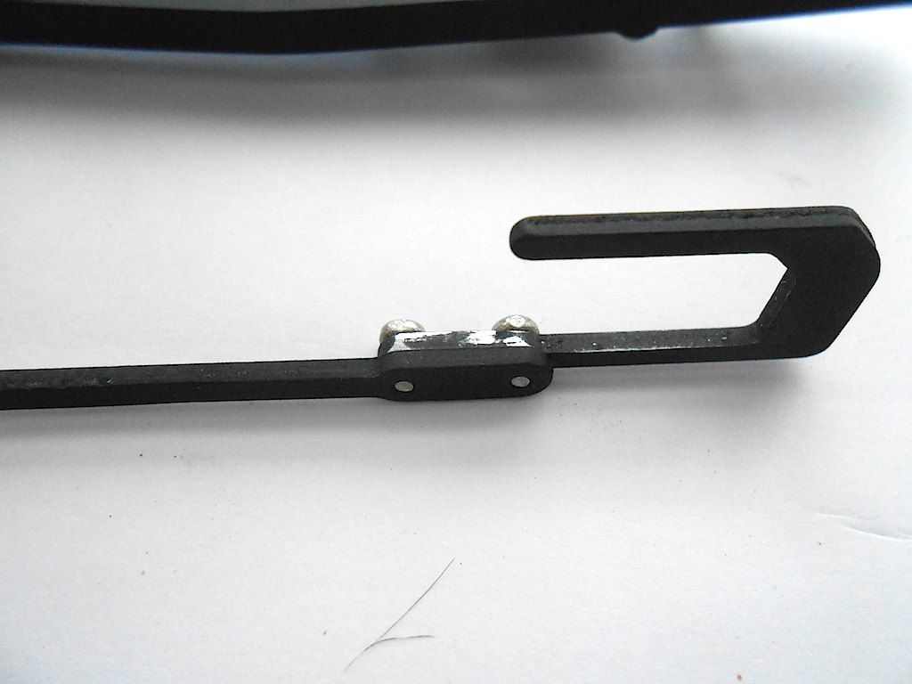 Have to pay attention here too. The bar attached to the sliding hook with those 2 screws connects to the other parts of the mechanism with a countersunk screw. So have to make sure it is installed the right side up. I succeeded in having both sides wrong. 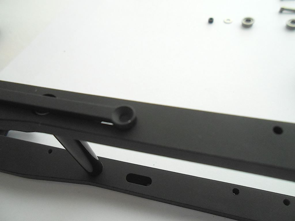 Next the rods of the mechanism. They are 64 mm long as per the manual. They are attached to the above rod through a bushing that goes into a sleeve through the frame. 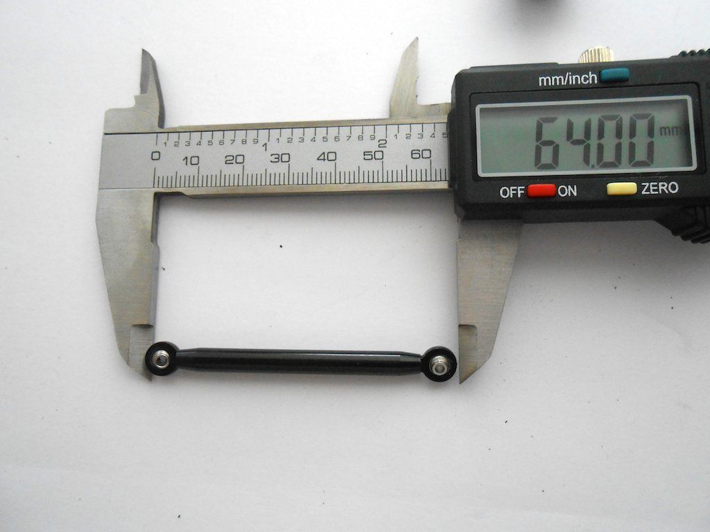 Here is one rod inserted. The second one is at this moment in the oven for 5 - 10 minutes at 180°C. One of the 4 balljoints of this package had a 3M thread. Didn't fit on the 2M thread rod. Easiest solution, some 2K End Fest glue and better than ever. 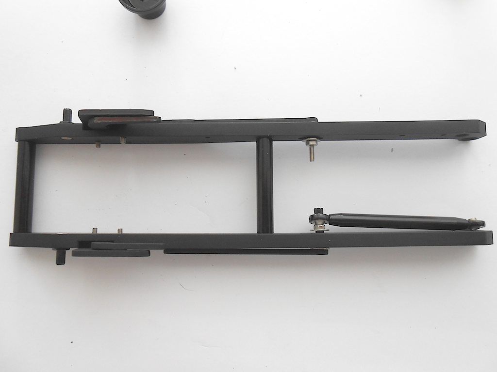 While the pushrod was cooling off, installed the axle and the wheels on which the containers will ride. Axle immobilised with cir clips ... smallest I've ever seen. Absolute nightmare to get on because I didn't have the right tool and had to use 2 needle nose pliers to open them up. 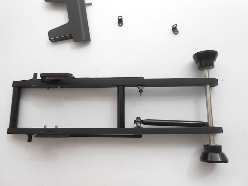 I was too fast installing the rollers ... they had to come off so I could attach the cover plate and the guide for the hydraulic line. 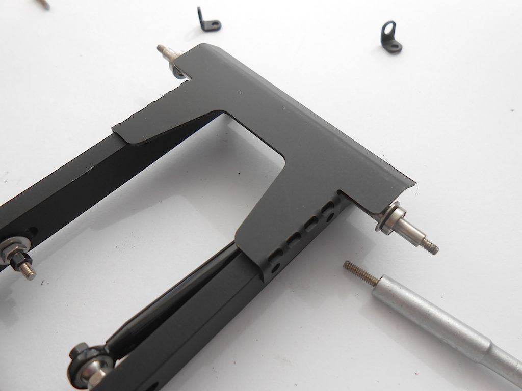 Finished view from top 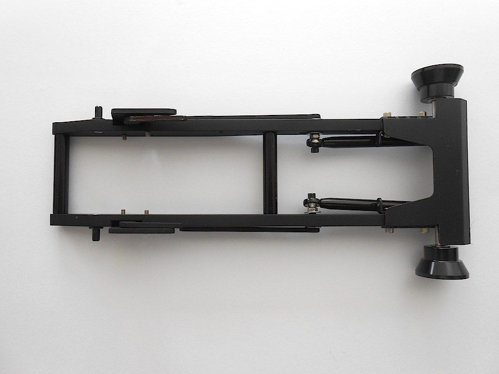 and bottom 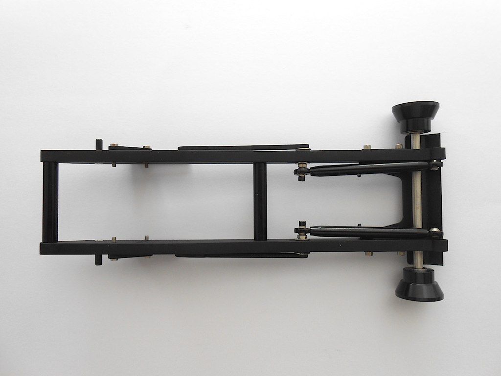 Cheers Stephan |
|
#58
|
||||
|
||||
|
WOW im glad your building this monster and not me
|
|
#59
|
||||
|
||||
|
Yes, sometimes I wonder why I started on this ... but all in all it's great fun. Anyway, you should be talking with your China Cat and that nice fleet of yours! Wished I only had a fraction of your skills in building / customising scale models
Stephan |
|
#60
|
||||
|
||||
|
Part 1 of the next step: assembling the arm and part of the hydraulics.
Only a few pieces for now 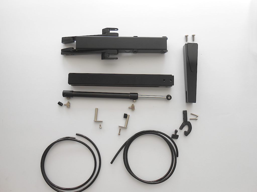 First we prep the hydraulic cylinder 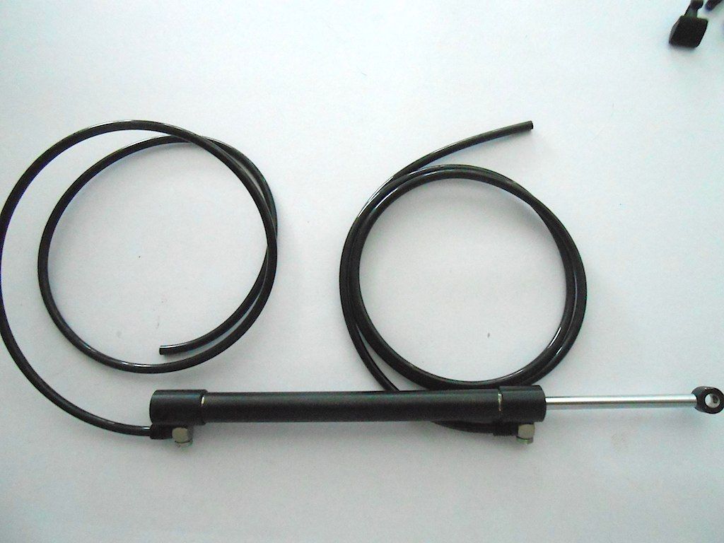 Then the hook 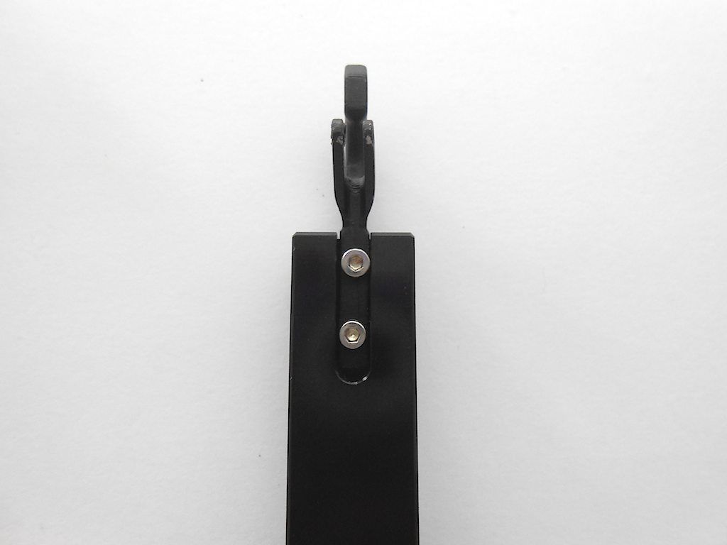 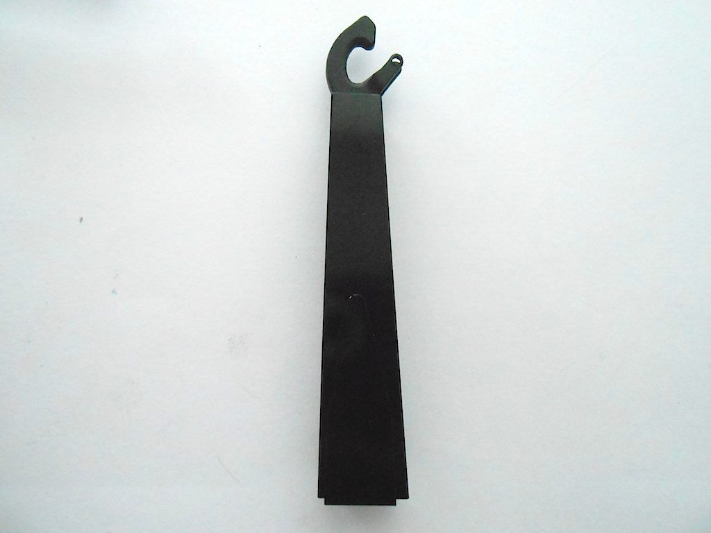 Then the above part gets bolted on the moving arm. The screws are recessed to allow for the hydraulic cylinder and not that easy to get into place. 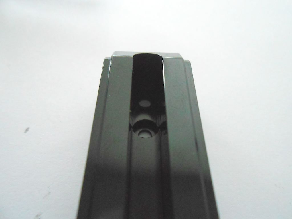 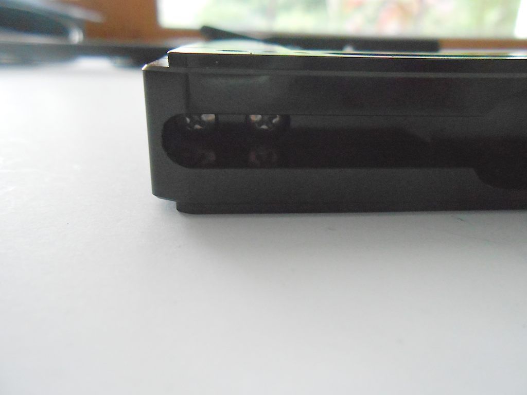 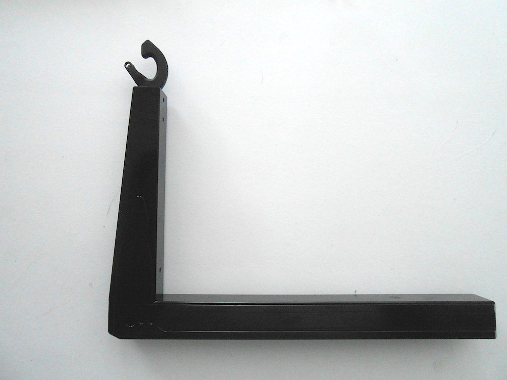 Next we have to insert/mount the hydraulic cylinder in the stationary part of the mechanism. This, because you have to slide the cylinder in a an angle because the nipples will otherwise not pass through. 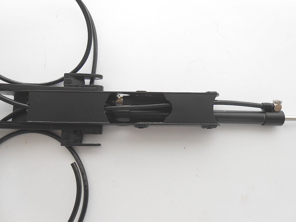 We also pass the hydraulic line of the top nipple through the provided guides 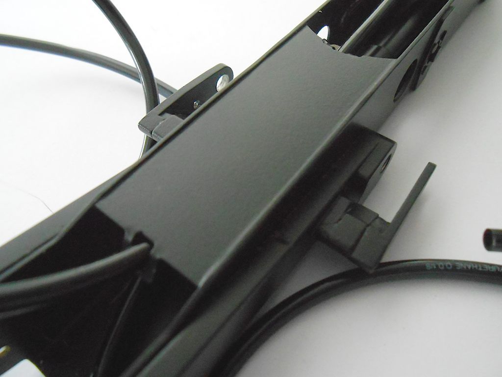 Secure the back end 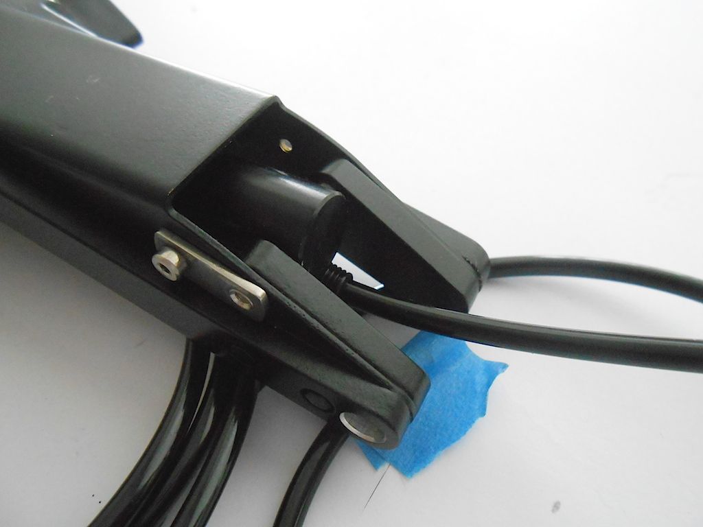 Pull out the piston 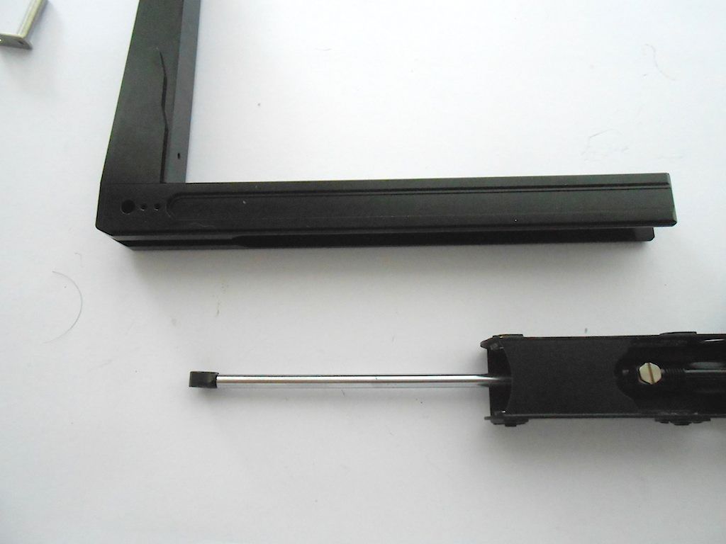 Slide the moving part of the arm into the stationary one (which goes smoothly) with due diligence and secure the other side of the hydraulic cylinder. (Before all this check the fit of the pins!) 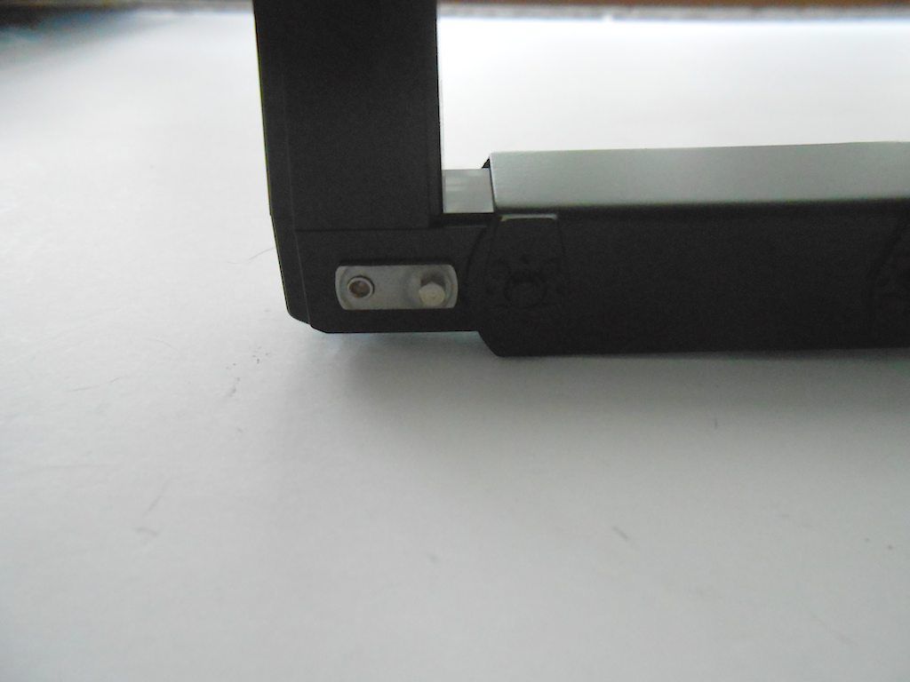 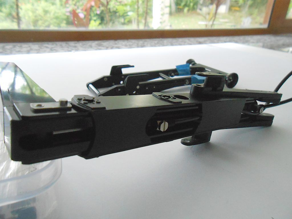 Some nice detailing 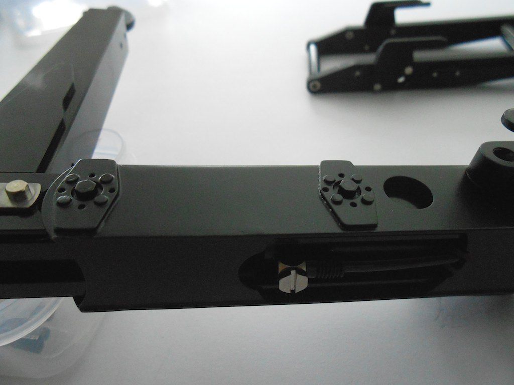 I also installed the provided lock on the hook ... Will remove it later. Nobody uses it because half the time it doesn't open because the counterweight is too light. 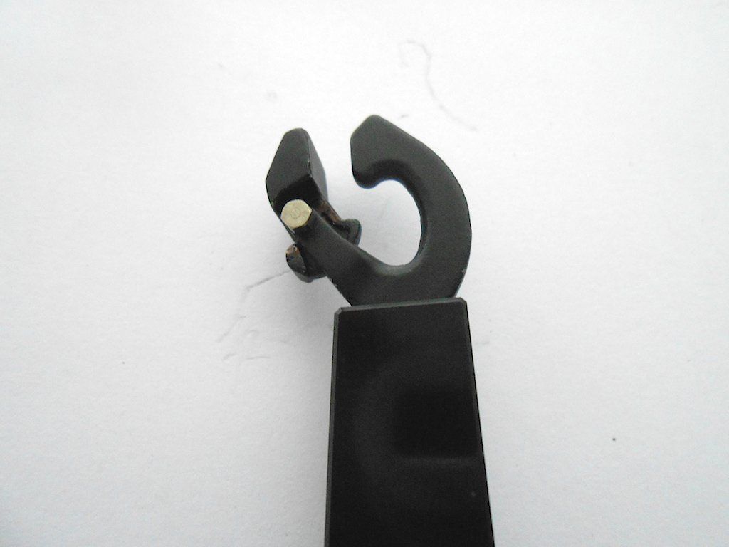
|
 |
| Tags |
| 8x8, arocs, scaleart |
| Currently Active Users Viewing This Thread: 7 (0 members and 7 guests) | |
|
|