
 |
|
|||||||
| Euro Style Trucks and Trailers A place for the Euro style trucks single and twin axle trucks and trailers... |
 |
|
|
Thread Tools | Display Modes |
|
#101
|
||||
|
||||
|
Hi Roundabout ... When I started on this I figured to bolt some things together on and off over the weekend for the next year or so, but turns out I keep putting things off to make time for this kit. Guess I spend about 2 - 3 hours every "session". Kind of addictive this thing ... actually been eying the bank account to see if I could swing another kit ... scary ...
1strodeo, nope not cheap, price is somewhere on page 2, post #36. But must say, worth every penny (or is that Eurocent). Just looking at the details and finish of the parts makes it worthwhile.
__________________
Cheers, Stephan (Rakthi is the one in the avatar) |
|
#102
|
|||
|
|||
|
Wow,, that is up there, ,but it really is a beutiful kit,, and super detailed.. I can see how it could be addictive.. But really isnt everything in this hobby. Good luck with it, can't wait to see the finished product.
|
|
#103
|
||||
|
||||
|
Hi 1strodeo, kind of can't wait myself to see it finished. But I don't want to rush it either.
++++++++++++++++ This part is the roof and the visor. This also includes the sound module that gets attached to the roof. This is still with the SMX one, If you check the ScaleART on-line shop, the trucks being sold now are with the smaller SM7. Maybe that one can go under the cabin. The usual picture of all the necessary bits (excluding the screws) 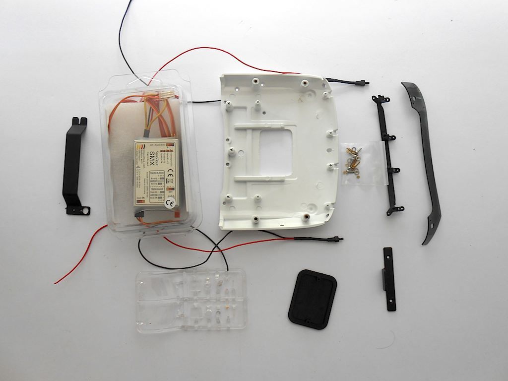 First I put the roof lights in. (This being an early production cabine, I had to enlarge the holes to fit the LEDs from 2mm to 3.5mm) 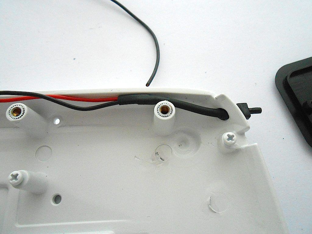 Then remove the lens from the mold (or whatever it is called) and test fitted. The visor opening needed to be filed a bit at an angle. 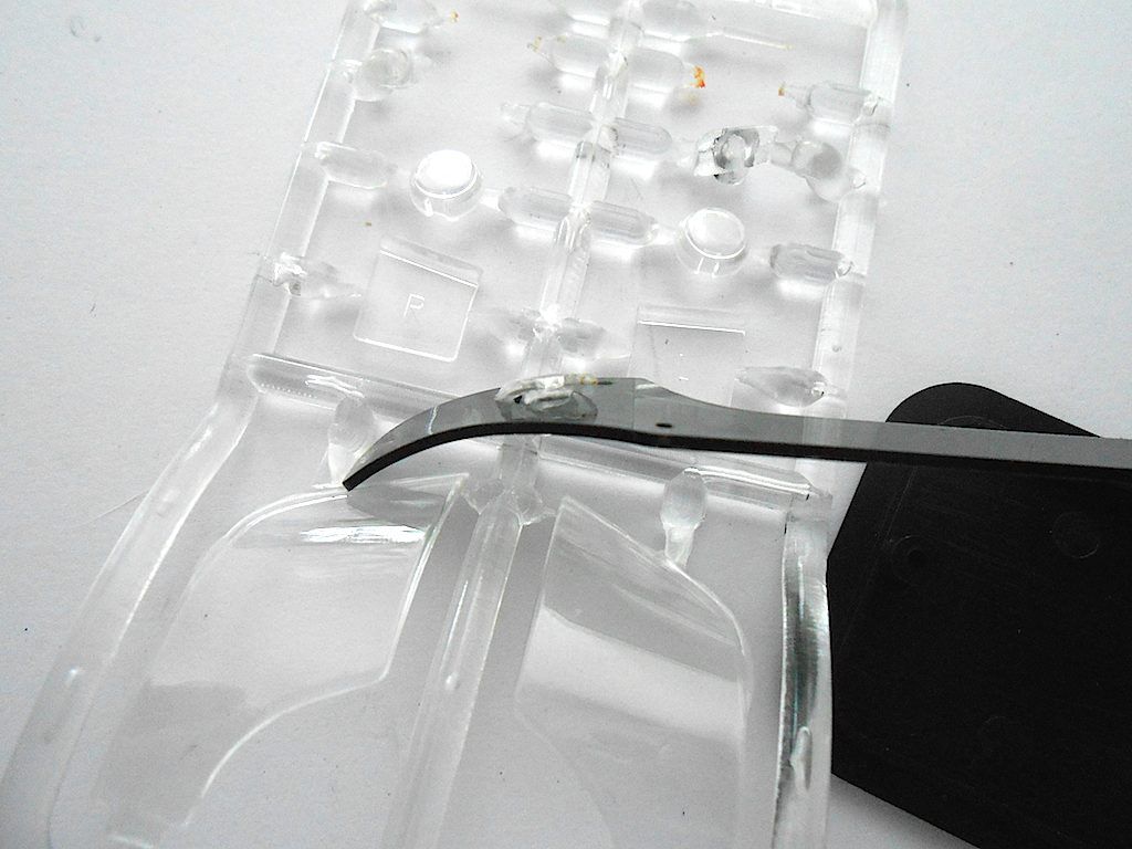 Having done this at both sides (hardly visible) time to attach the visor to its support. 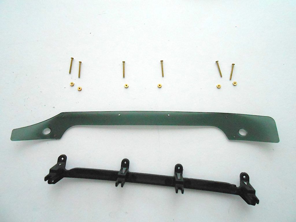 Easiest is to start with the 2 in the middle and then do the ones at the corner. (the size of the nuts/screws make this one of those colourful language moments  ) ) 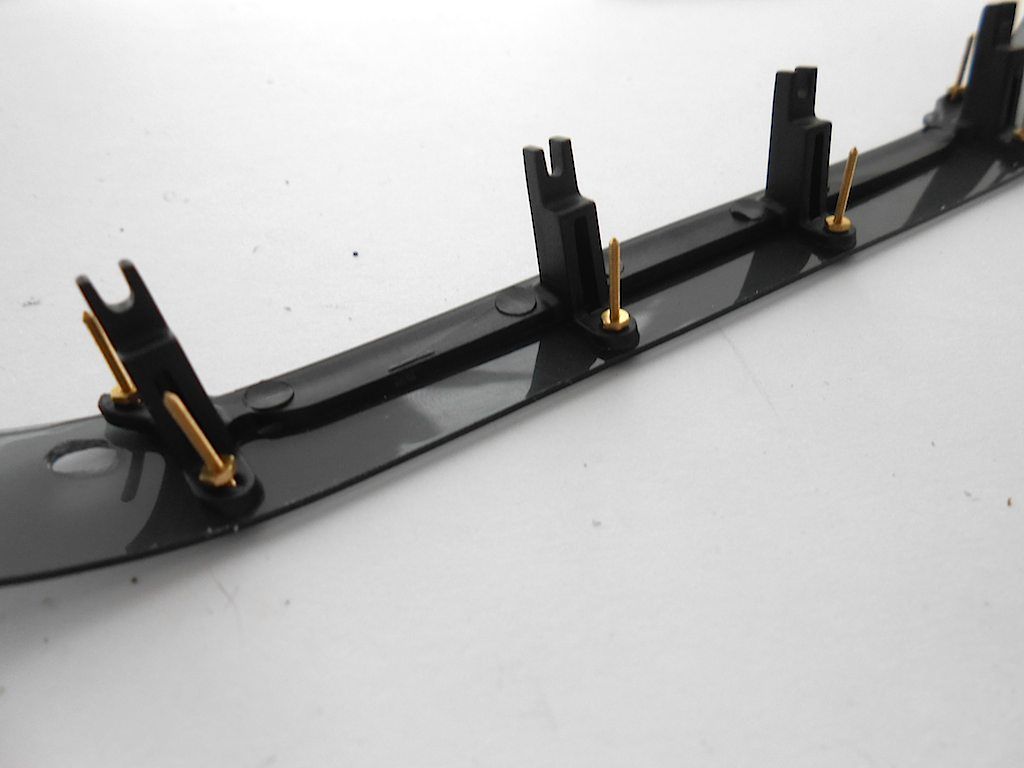 Shorten the screws and then tighten the nuts with the 2.5mm driver 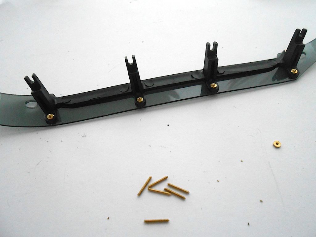 Mixed some 2 component glue to fix the lenses for the LEDs 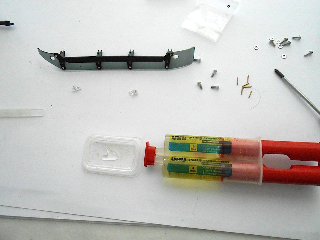 Applied with one of those dental tools with the fluffy bit cut off. 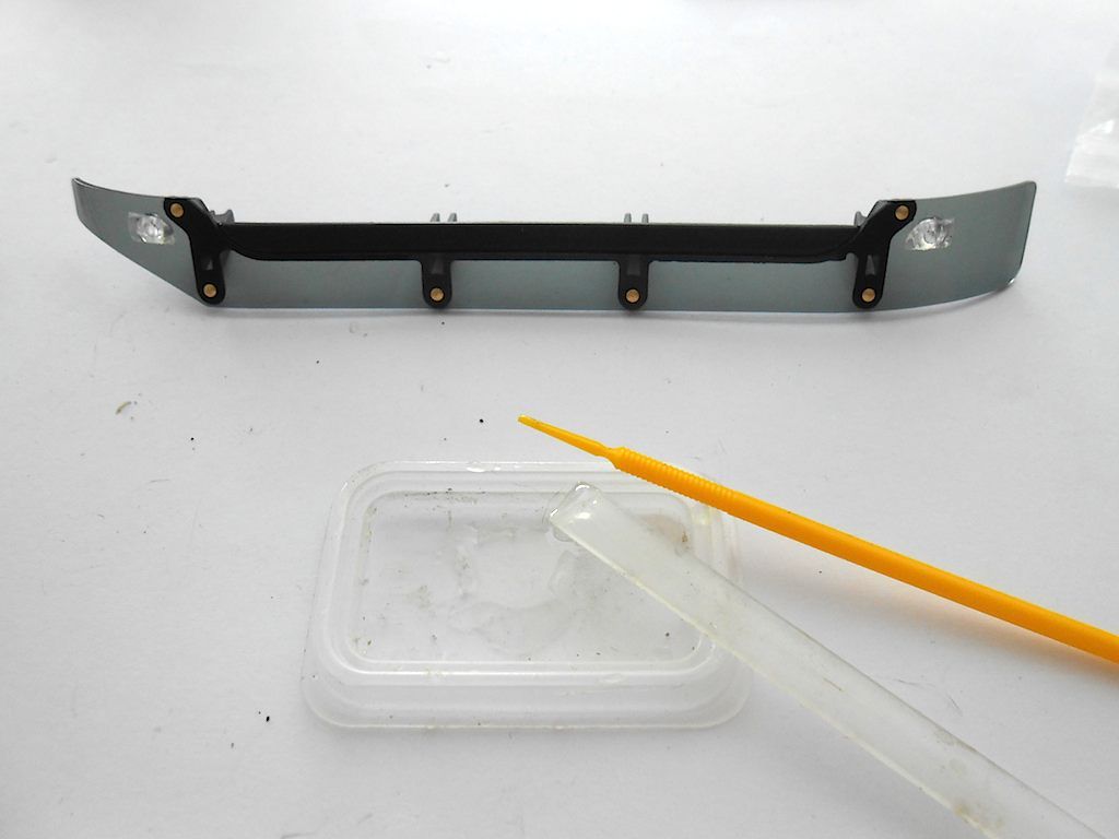 Whilst waiting for the glue to set, continue with the rest of this assembly The roof hatch and its fastener. This is partly L shaped so the sound module can not shove forwards. Gets screwed together with 2 self tapping countersunk screws. 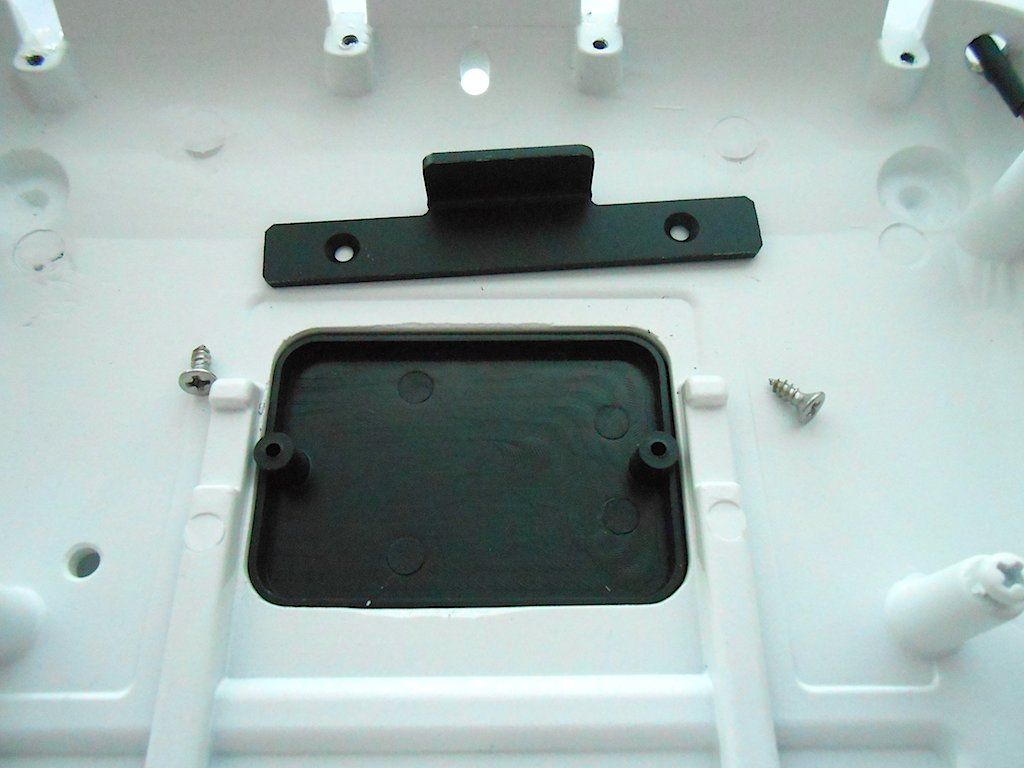 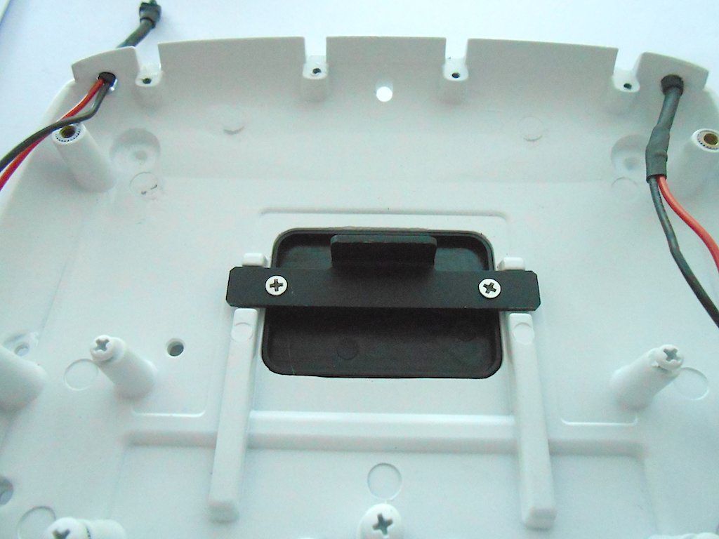 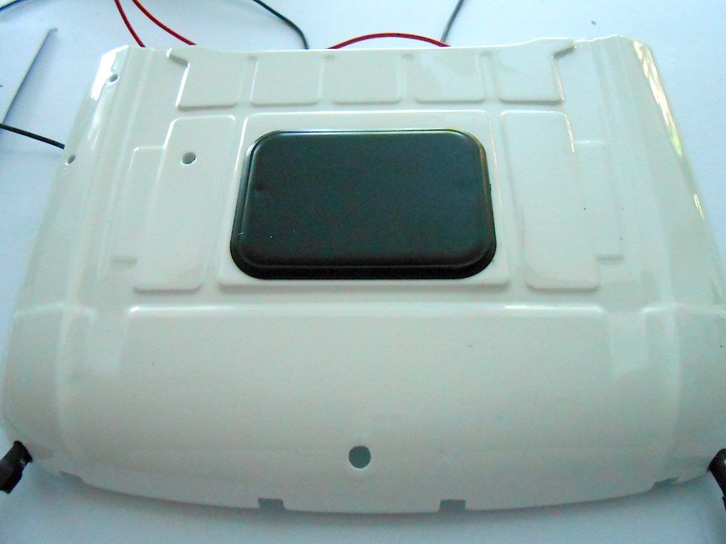 Followed by the sound module ... can't make up my mind how to install it ... 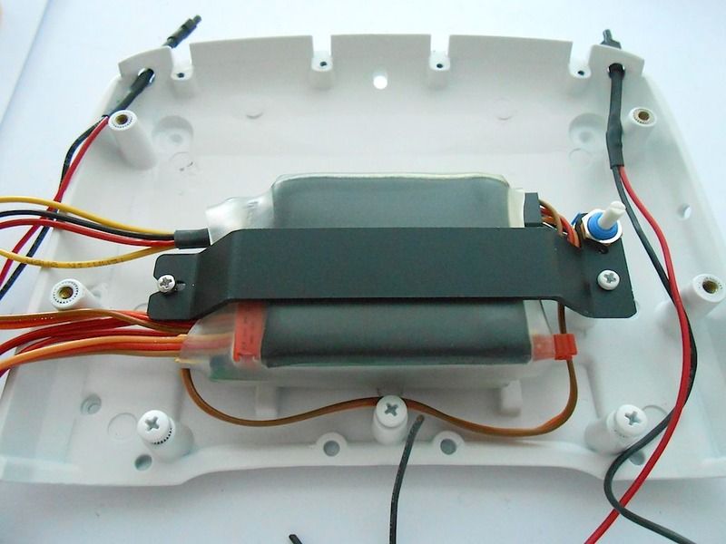 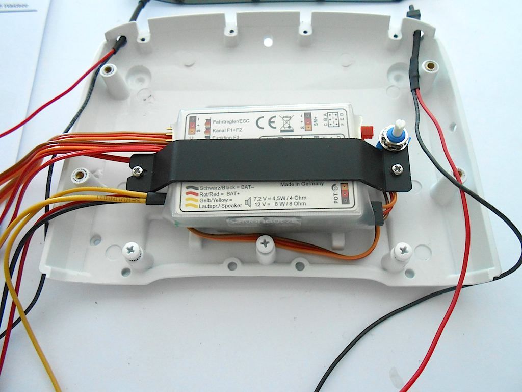 Can go in both ways ... will have a look see at the paperwork that came with the electrical package to see how and where all those cables end up. And I better find a way to organise them a bit too. As for the visor ... the glue might be fast after 20 minutes, but it will take 72 hours for it to really set ... Bummer ... figure I better wait, I tried fitting it, but even after one hour the LED still succeeded in pushing the lens a bit out. And yes, I filed the sharp ends of those screws. 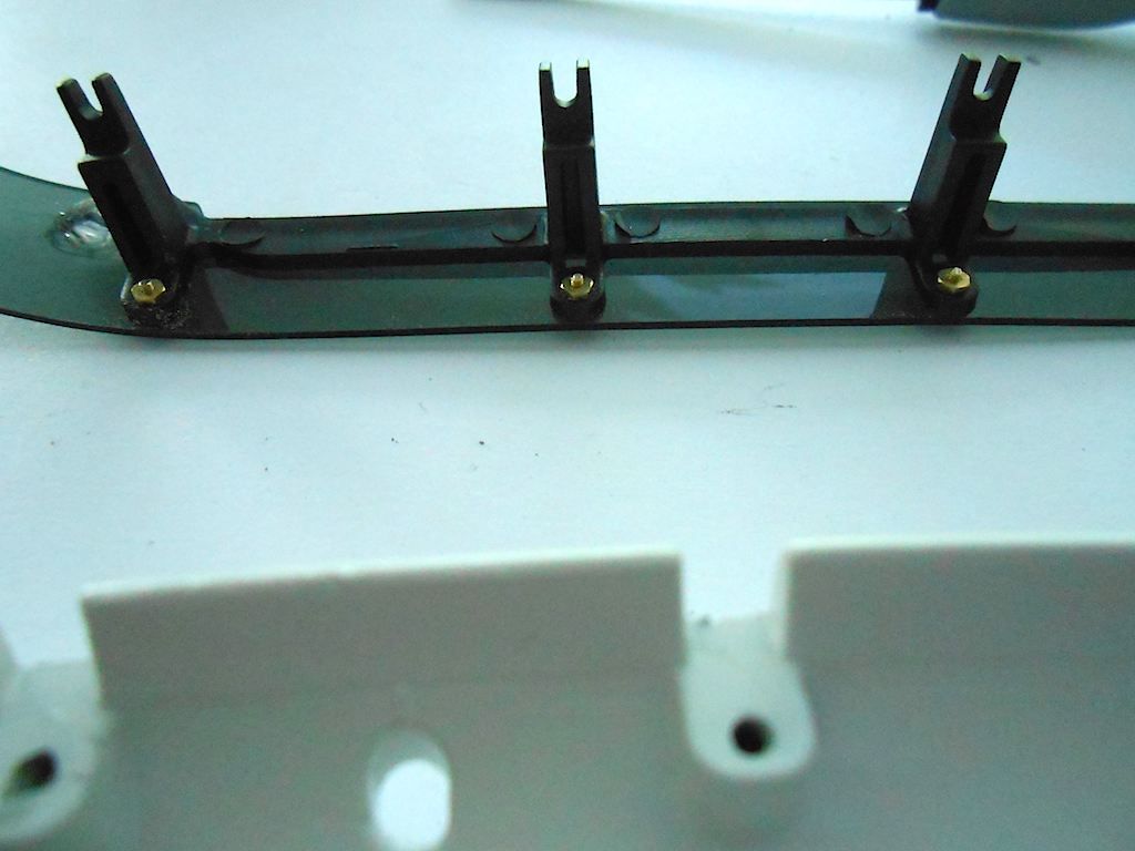 Guess I will pass the time with sorting wiring, prepping back of cabin and starting on the seats and other interior parts. Till next posting Stephan
__________________
Cheers, Stephan (Rakthi is the one in the avatar) |
|
#104
|
||||
|
||||
|
Hi Stephan,
this is really a fantastic building report! - The cables of the sound module beneath the roof you can organize for example in this way: 5_AROCS_FH_Dach_2014_11_30 (4).jpg 6_AROCS_FH_Rückwand_2014_11_30 (13).jpg I'm looking forward to your next update and stay tuned. 
__________________
Greetings Christian You can find some of my RC-models on To view links or images in signatures your post count must be 10 or greater. You currently have 0 posts. Normally I´m speaking german, please forgive my mistakes in English. |
|
#105
|
||||
|
||||
|
Ohhh ... I can´t see my uploaded pictures! ... Hmmm?!? ... I'm probably doing something wrong.
You also can have a look on my Facebook-Site. There you'll find a photo album which shows the assembly of the AROCS driver´s cab. You might find some pictures concerning the cables. Link to the photo album: http://www.facebook.com/media/set/?s...4207815&type=3
__________________
Greetings Christian You can find some of my RC-models on To view links or images in signatures your post count must be 10 or greater. You currently have 0 posts. Normally I´m speaking german, please forgive my mistakes in English. |
|
#106
|
||||
|
||||
|
Hi Christian, thanks for the link! Will be a great help now and further in the build. Now I can double check my interpretation of the technical drawings.
Looks like a good thing I finally found a place that sells shrink tubing in different sizes here on the island. Cheers, Stephan
__________________
Cheers, Stephan (Rakthi is the one in the avatar) |
|
#107
|
||||
|
||||
|
So yesterday I finished of the roof and the rear of the cab
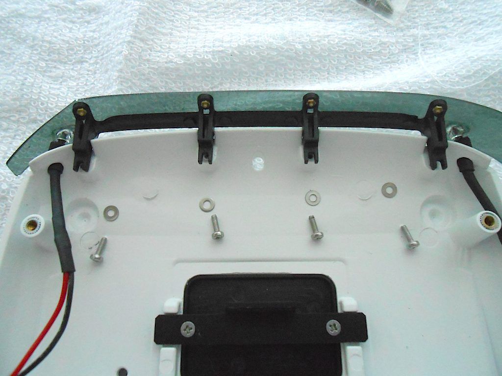 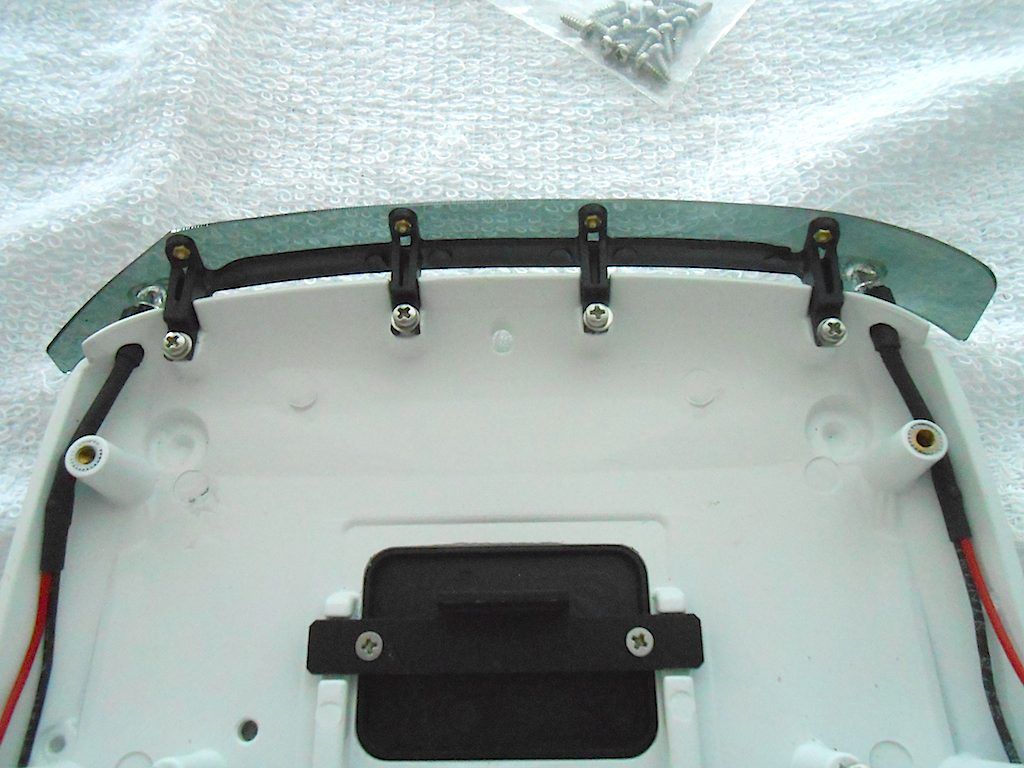 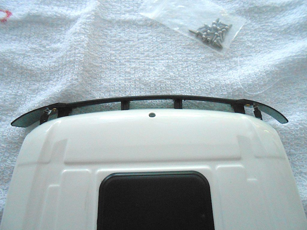 Re-installed the Sound Module with the cables split up and put into shrink tubing as per Christian's suggestion. 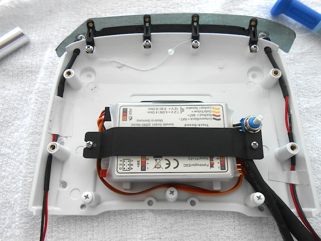 Then on the back of the cab 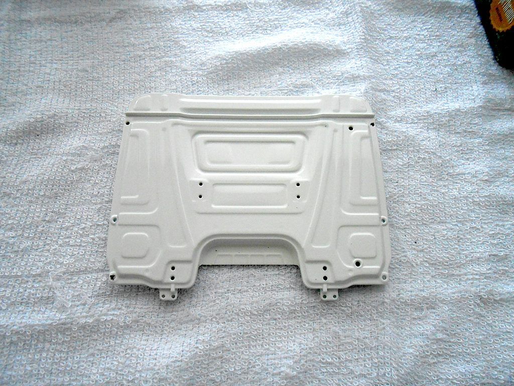 One of the 2mm screw holes not completely drilled through 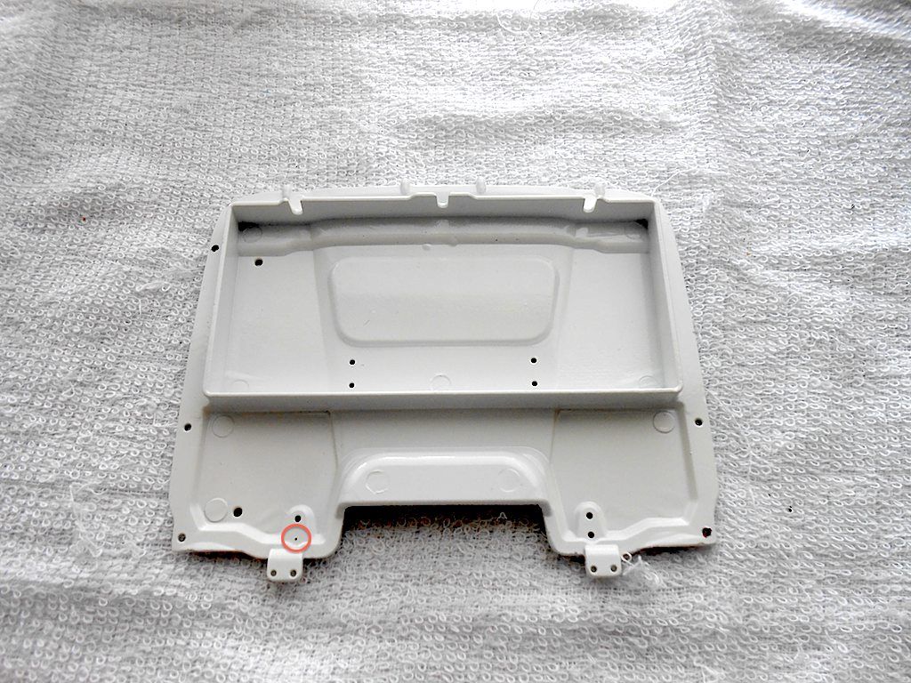 The parts that need attaching. (the rectangular air vents I glued in with super glue) 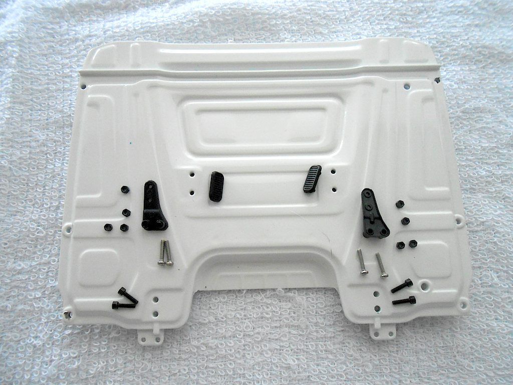 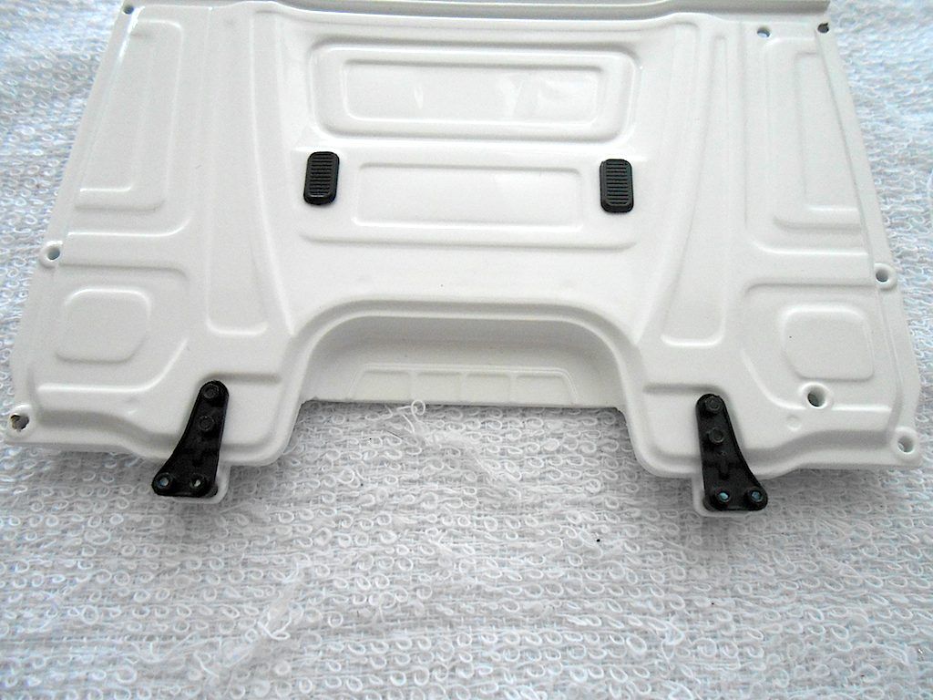 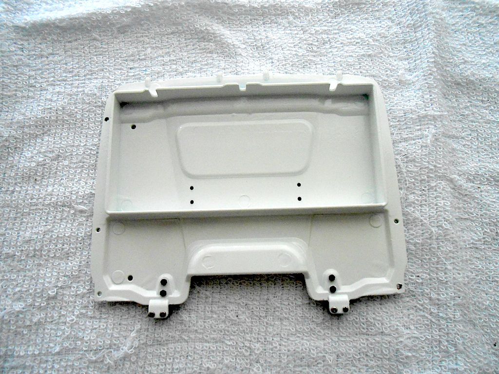 This is where it locks onto the chassis. 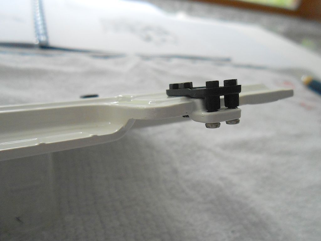 Next part is the air inlet Filed the back of the grid a bit down so it fitted a tad better. 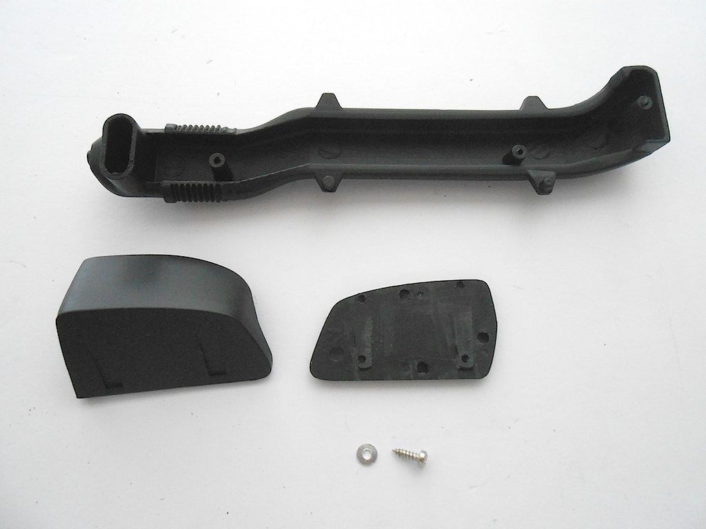 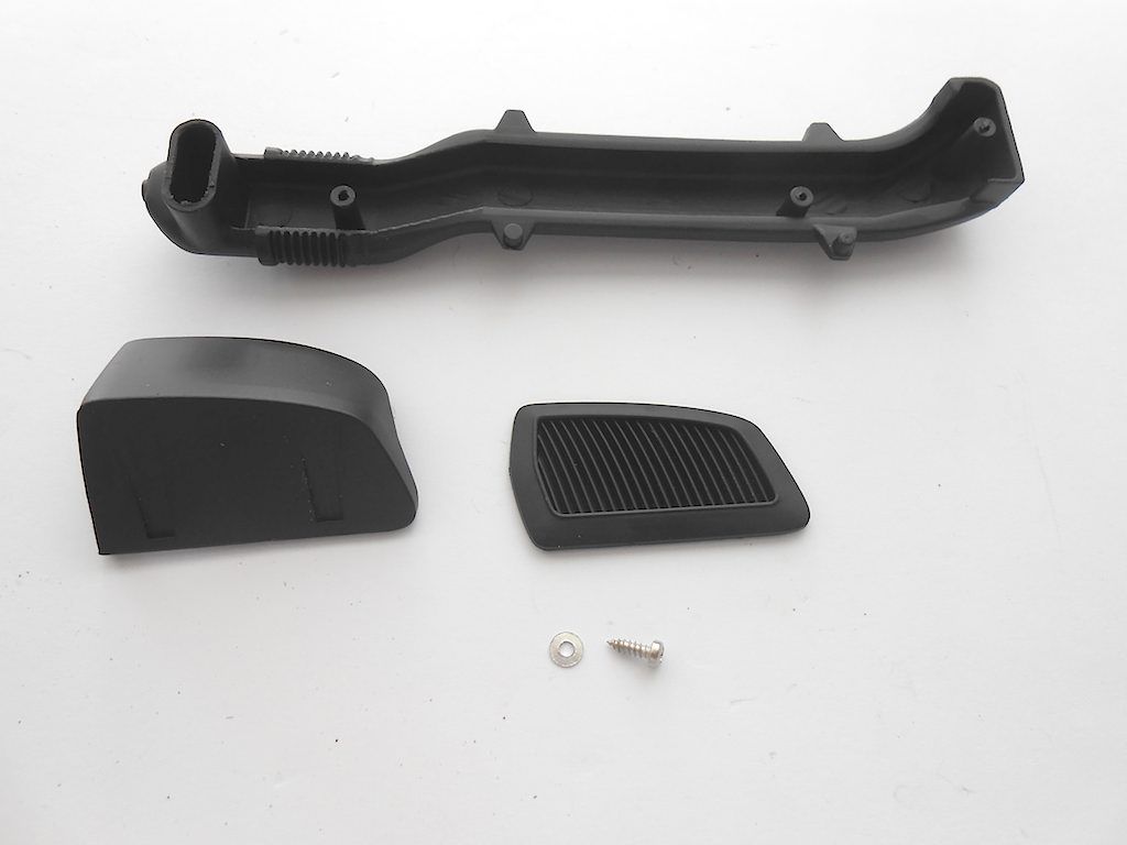 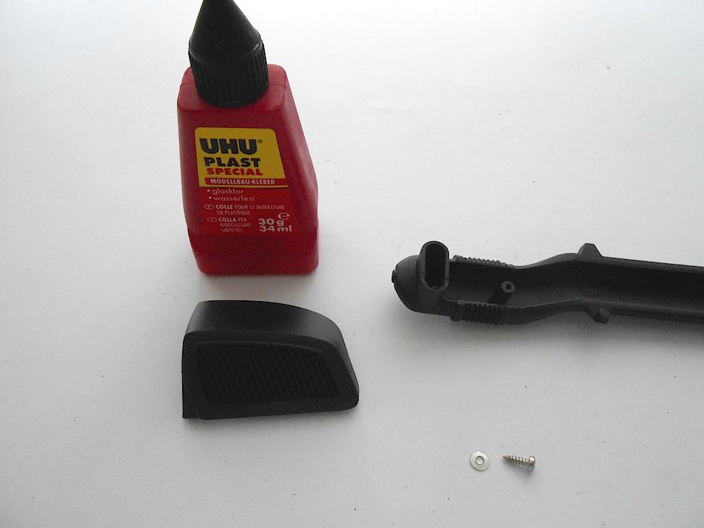 Only one self tapping screw and washer used in this 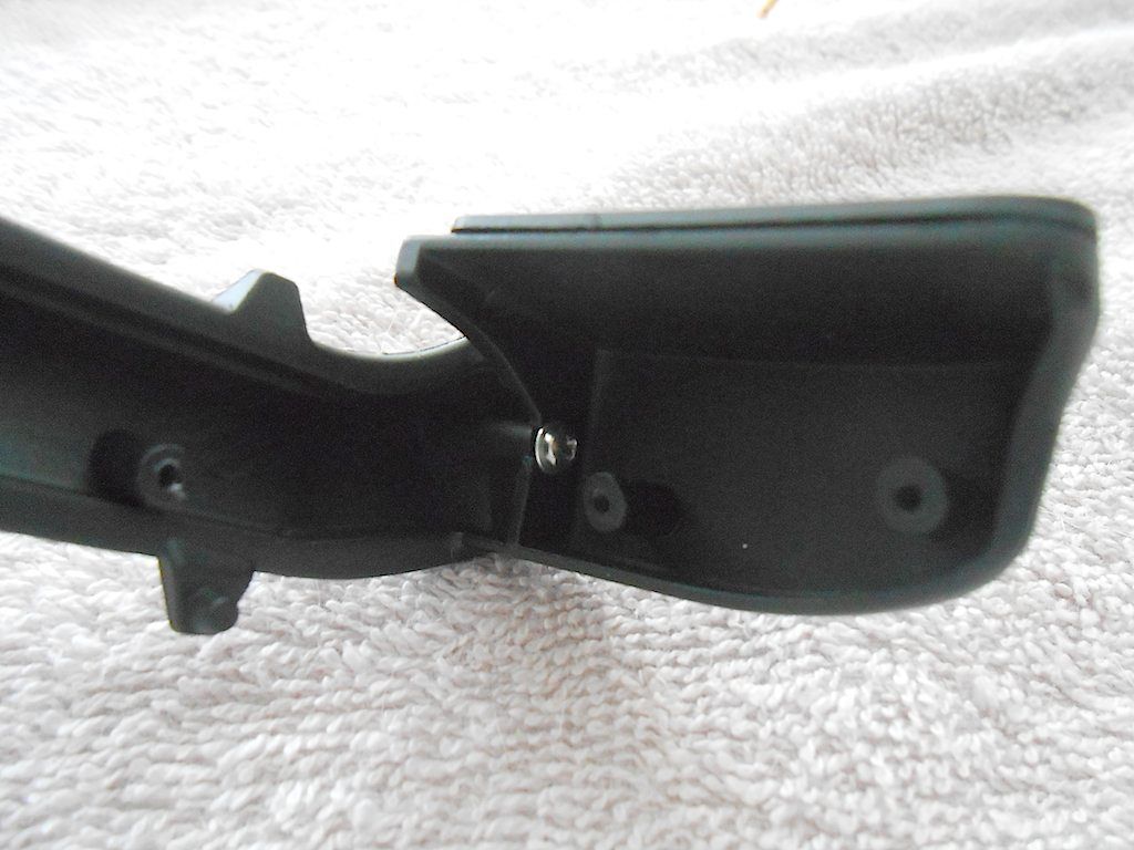 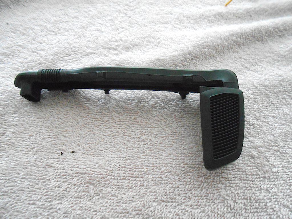
__________________
Cheers, Stephan (Rakthi is the one in the avatar) |
|
#108
|
||||
|
||||
|
Today, I started off with the SMX Sound Module ...
Took it off the roof again and had a good look at it. Turns out the bit under the cooling plate is basically empty with the plate seemingly just sitting on one chip. I figured it made more sense then to install it with the heavier parts towards the roof. 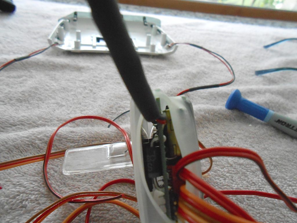 I also took off the shrink tubing I had put on yesterday. I had tested a couple of times, but unlike Christian (Newcomer_2) I could not get the wires with the shrink tubing to go through the cable channel provided. I guess the "Made in China" tubing available here is thicker and less flexible. So ended up bundling the wires with bits of shrink tubing. The top wire bundle is power and speaker, the middle single one is Function 3 which is not used according to the electrical plan, and the bottom bundle are the rest of the wires. (hookup esc etc) 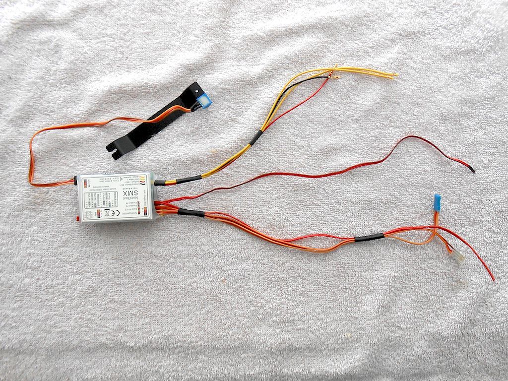 So I tried to program it as in the Servonaut Manual ... I left the bottom bridge on the pins for the in-line 6 cylinder engine (checked MB website, and Arocs have an in-line 6 power plant), and took out the top pin to start the programming. (wanted to turn off the peep-peep when going backwards - can't stand that sound) 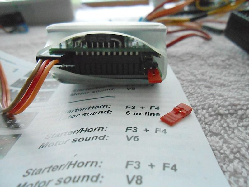 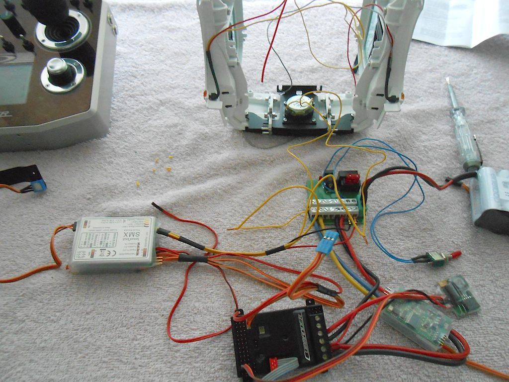 Didn't cut off the cable for Function 3, just tucked it under the unit in the space left there by the roof hatch. 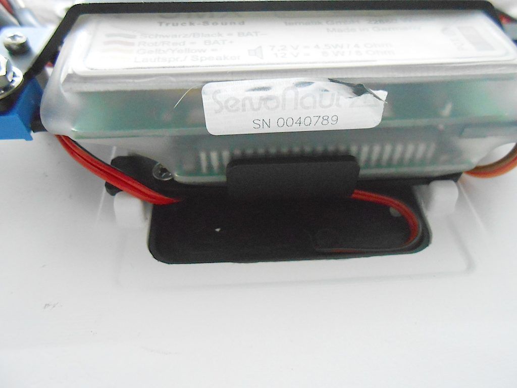 Roof goes on with 4 M3x8 screws and some lock washers. 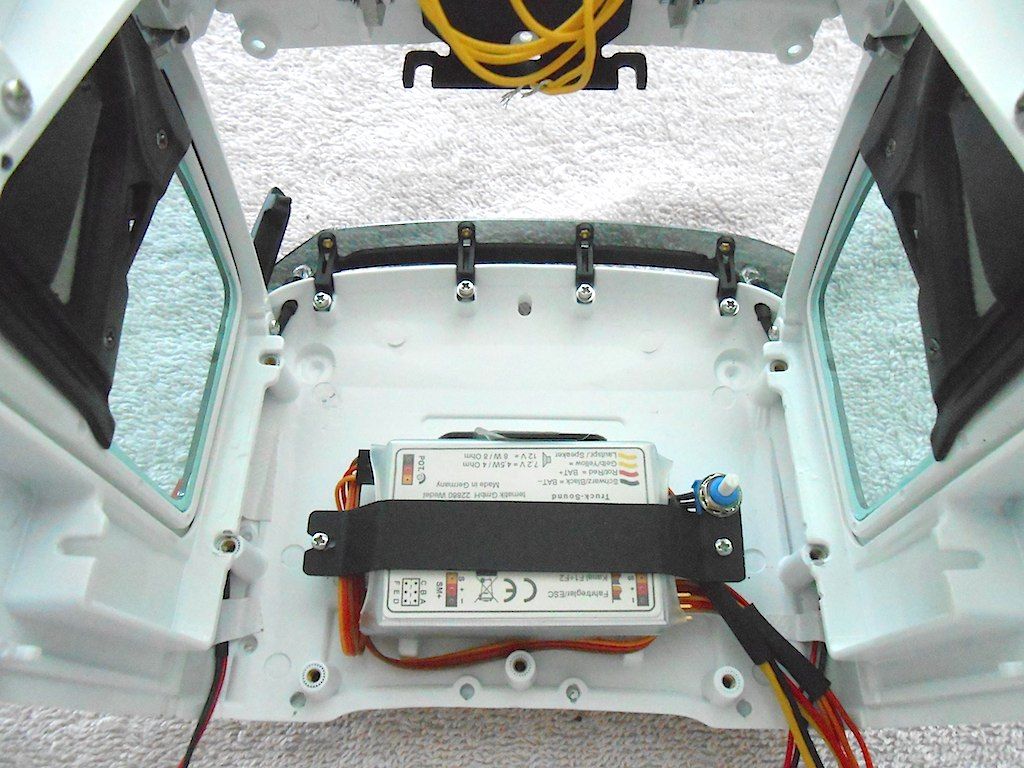 Then the back goes on. The little pins go in the holes provided. The wires get tucked into what will become the wiring channel. 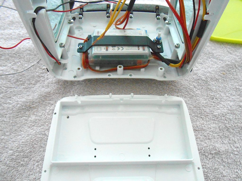 The reason I had to take of the shrink tubing is that I couldn't get a decent bend near the roof. This way it was easier to control. 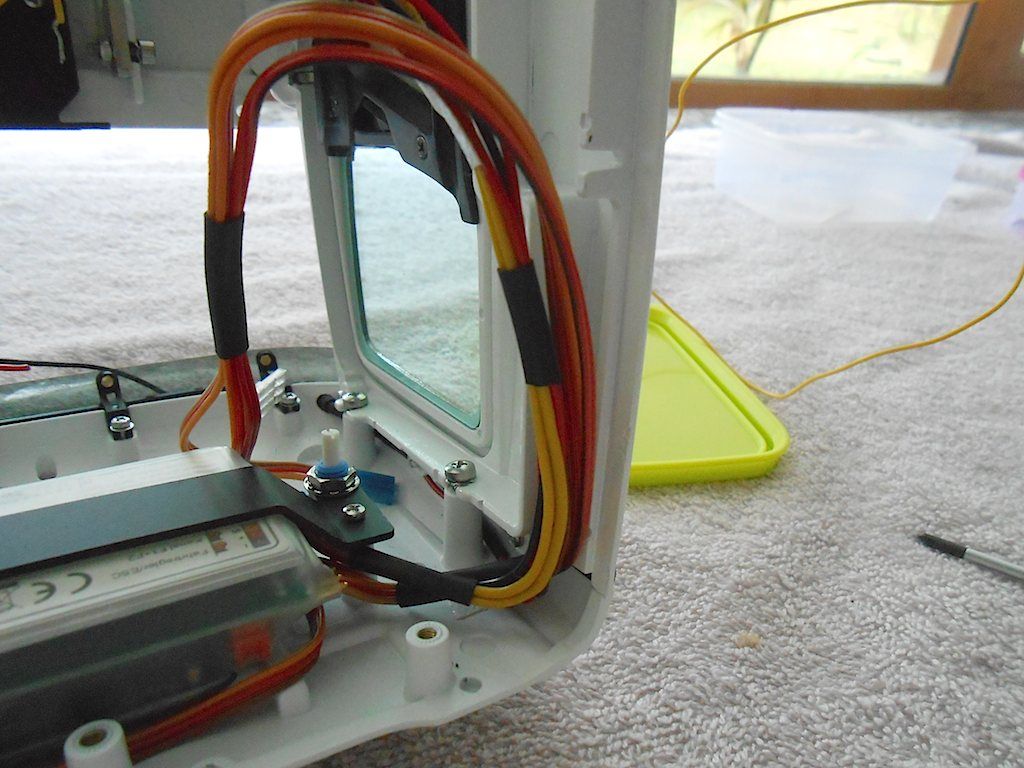 Back bolts onto the roof with 2 m3x6 and 1 M3x8 (in the middle). It bolts to each side with 2 M2x8. 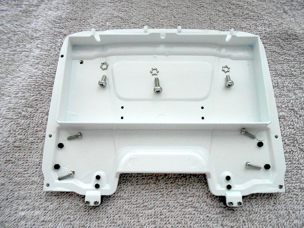 The m2x8 go into these provided slots on the sides. 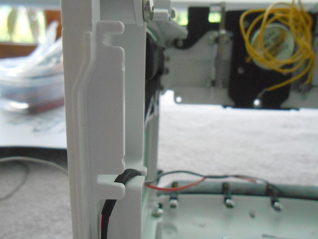 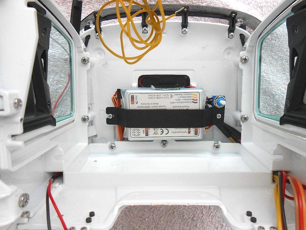 Continued ...
__________________
Cheers, Stephan (Rakthi is the one in the avatar) |
|
#109
|
||||
|
||||
|
Tried the cabin on the chassis.
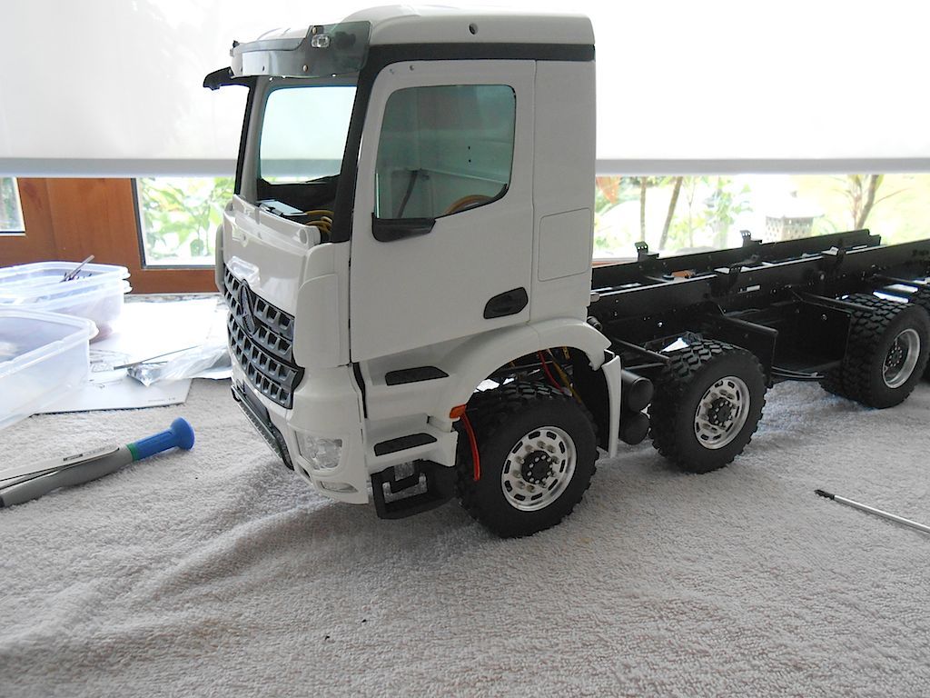 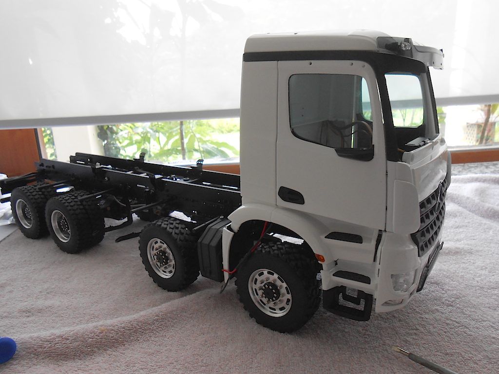 Tested the locking mechanism 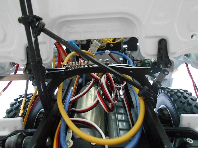 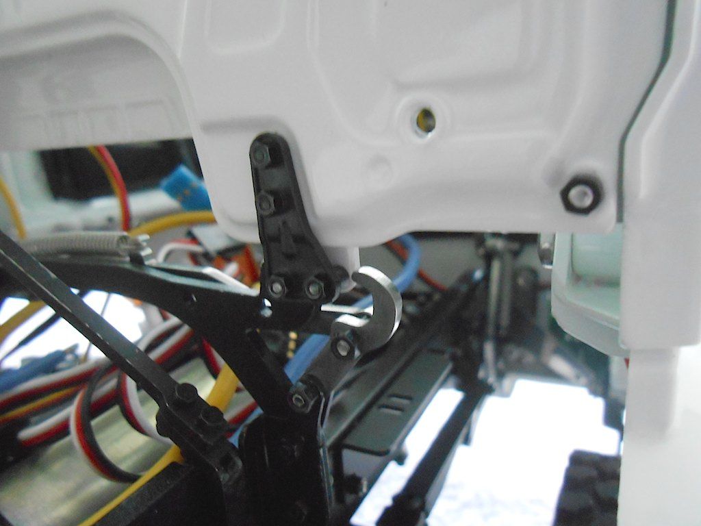 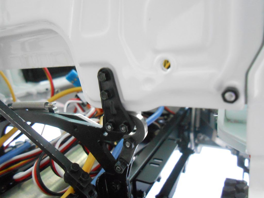 Now time for the air intake to be put on. (takes 4 M2.2x6 self tapping screws). 2 in the roof and 2 in the back. 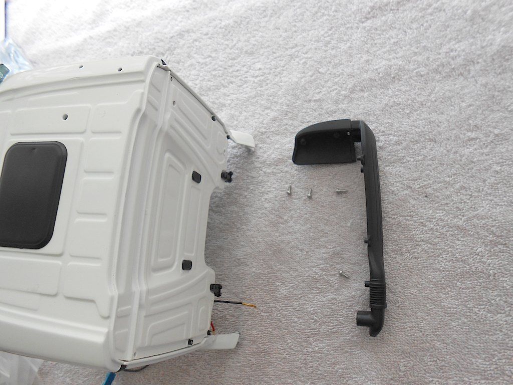 Alerted by the pictures in the link Christian provided, I knew there would be a problem with the locking mechanism interfering with the intake. So only temporary screwed on with 2 screws. 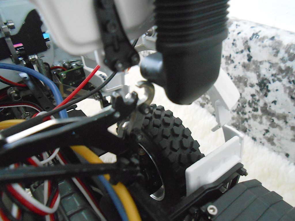 So a bit of plastic had to go. (the cut will be cleaned up) 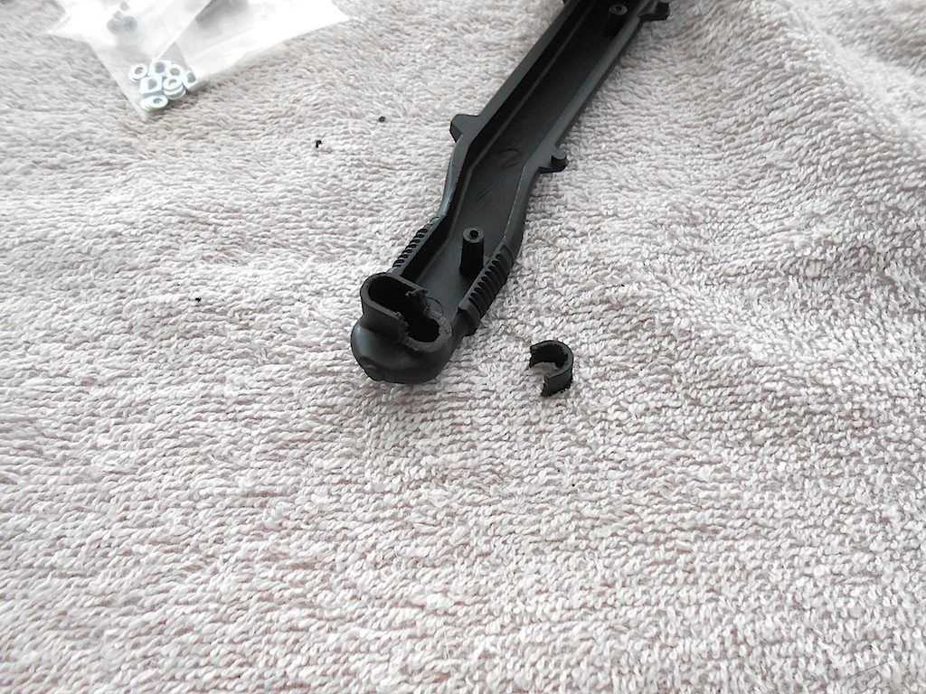 Now proper install of the intake. Found that it was easiest to first do the top part. 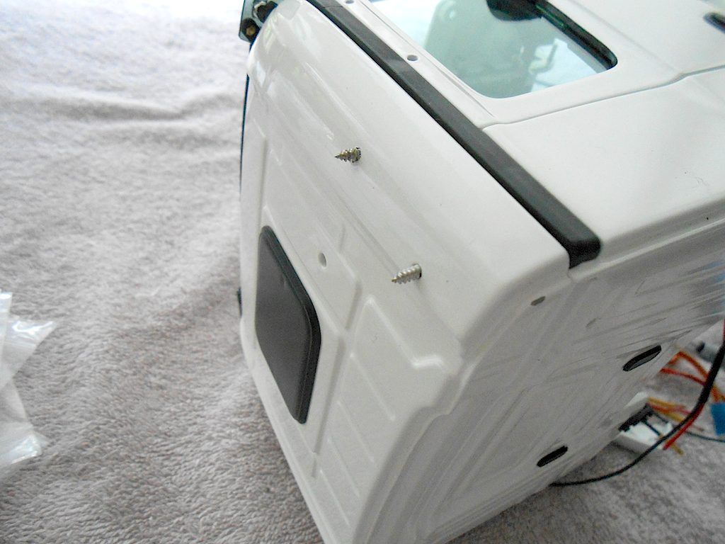 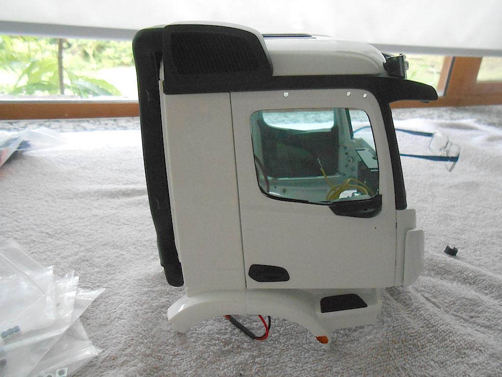 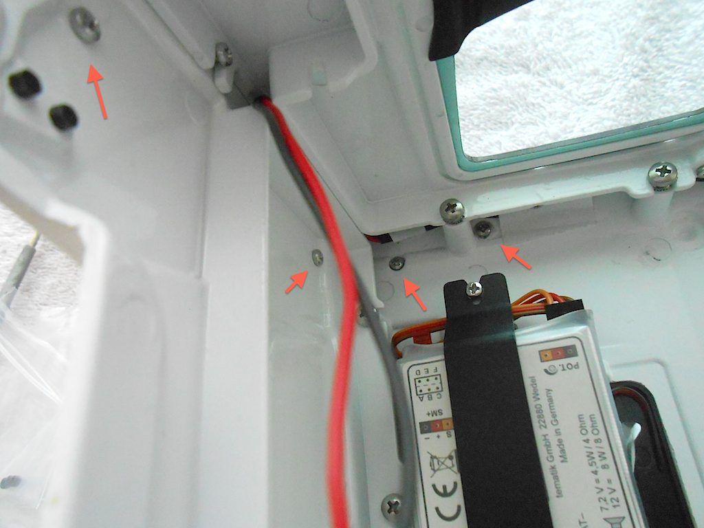 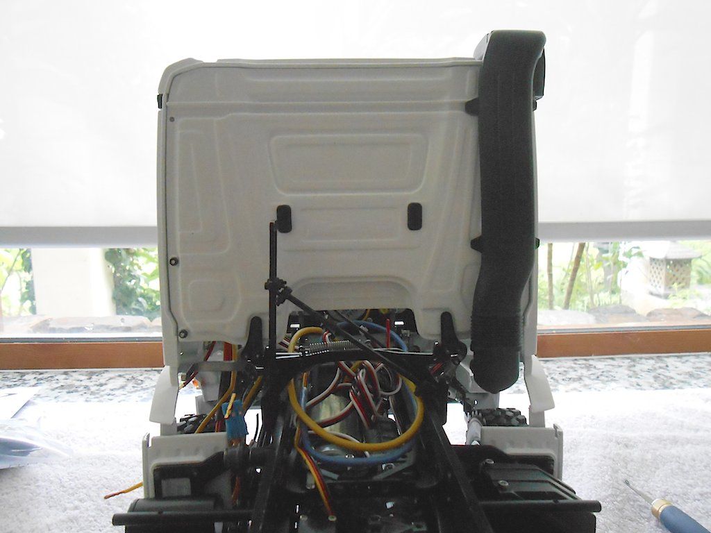 Next up would be the interior of the cabin.
__________________
Cheers, Stephan (Rakthi is the one in the avatar) |
|
#110
|
||||
|
||||
|
On with the next group.
We start of with the windscreen. This could not be installed earlier otherwise wouldn't be able to attach the intake. Consists of a window, front cover and 3 self tapping screws 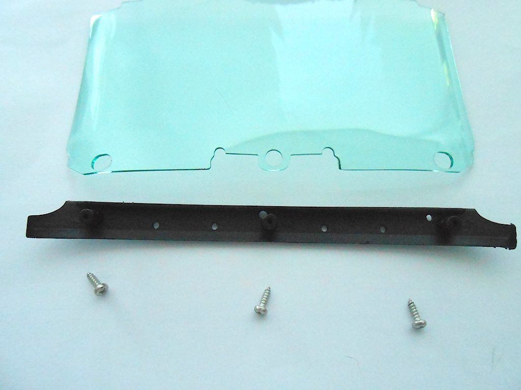 The window needs to be bend a bit to get behind the sides. Also need to be aware of good positioning at the roof. I got mine stuck wrong on one of the screws of the visor. And I got some paint damage in the lower corner form not paying attention when bending/inserting it. Lucky the black cover goes over it. 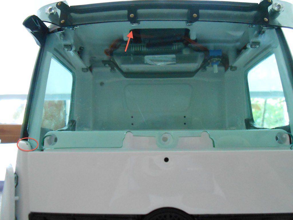 Gets all fastened on the inside. Access through the bottom. Was very happy with the bendable extension I have. Was worried the screwdriver would jump and scratch the plastic. 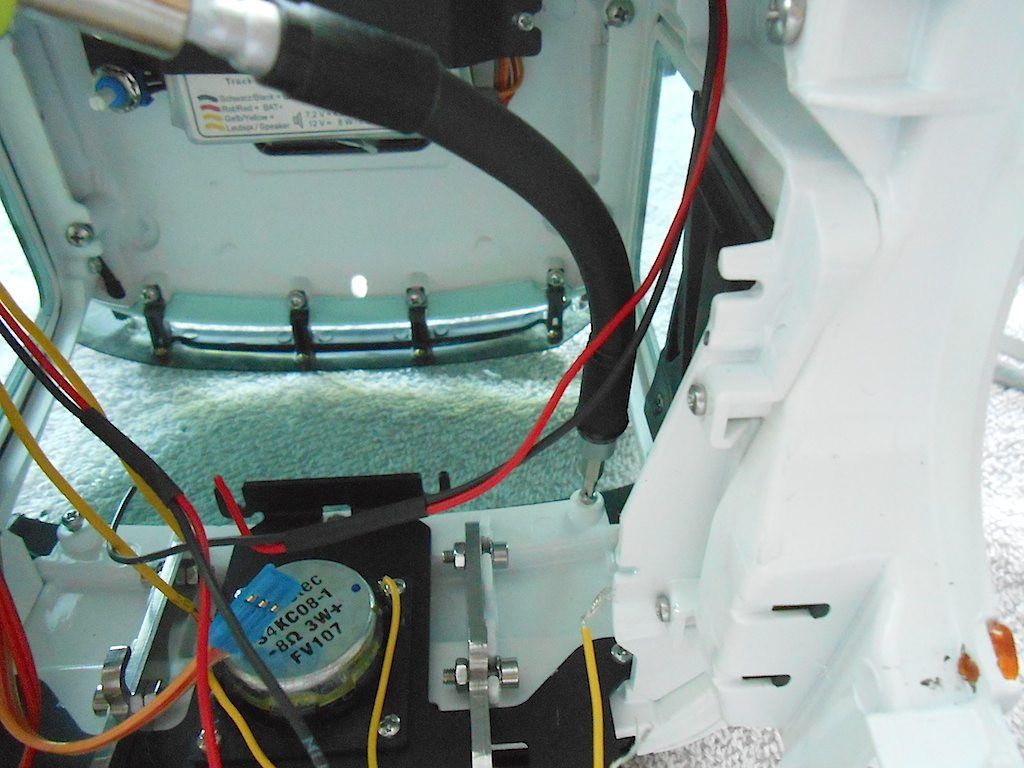 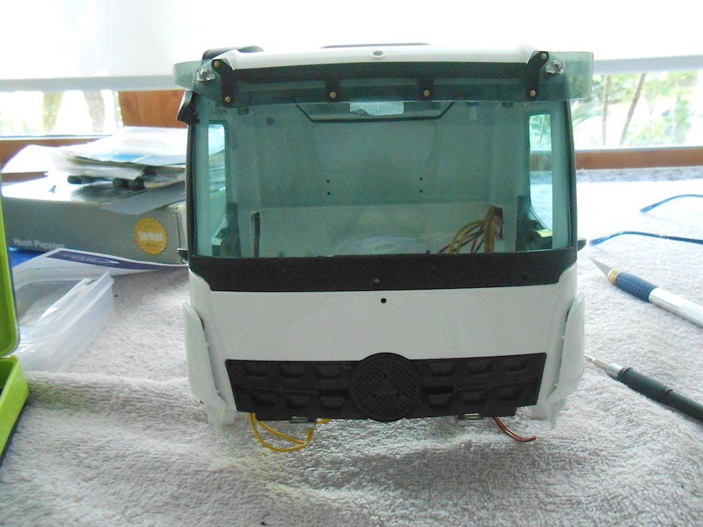 Next the floor parts. Assembled with countersunk screws. 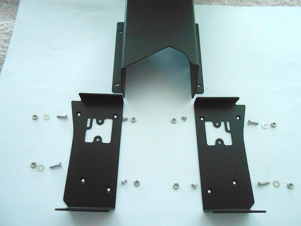 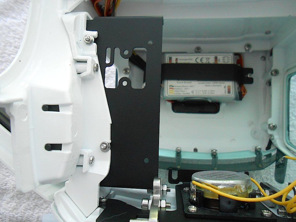 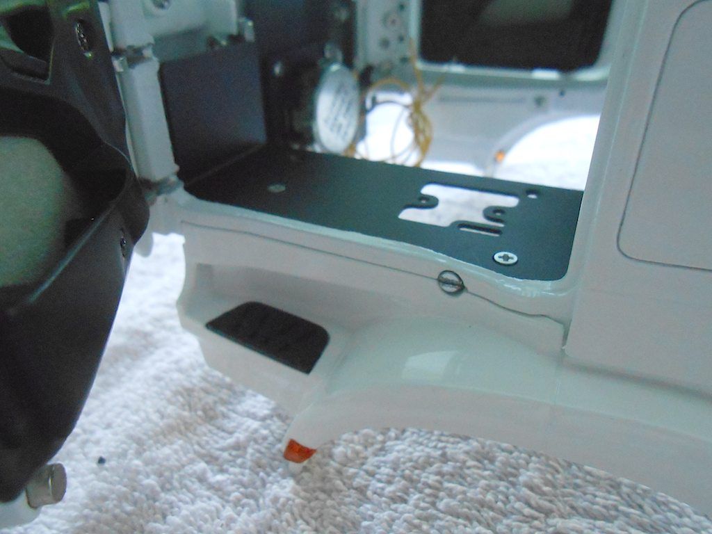 No way I can glue the optional carpet on when installed in cabin ... 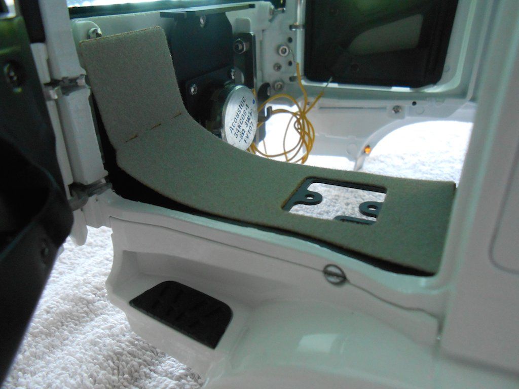 So attach the needed screws. Already complicated enough getting the "carpet" on straight without having to deal with screws all over the place. (Carpet can be repositioned if not right first time around) 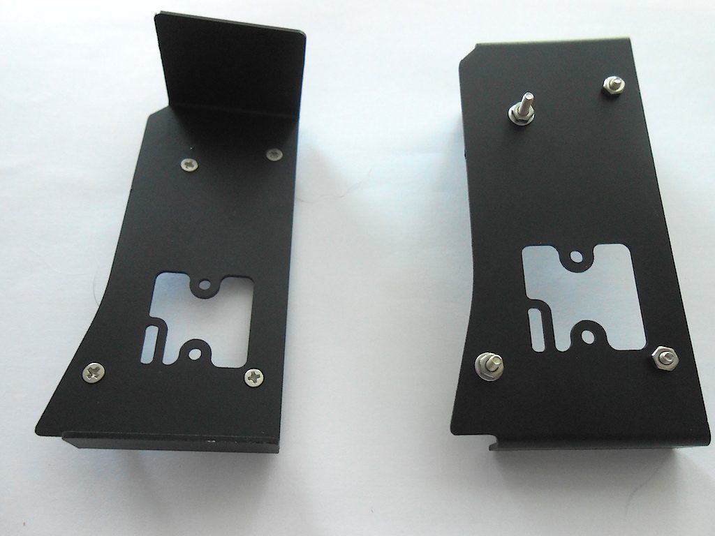 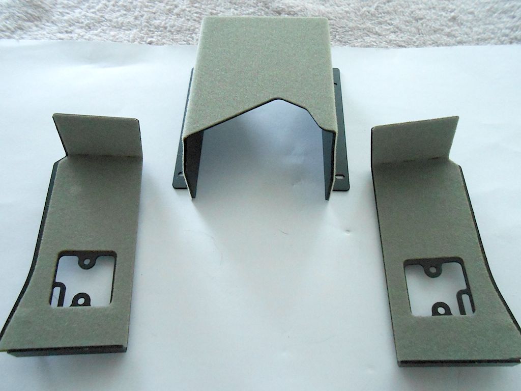 Both side pieces attached first, and the center piece goes in from below. Had to loosen the nuts from the side pieces to make it easier to get the center bit in place. Very tight tolerances. 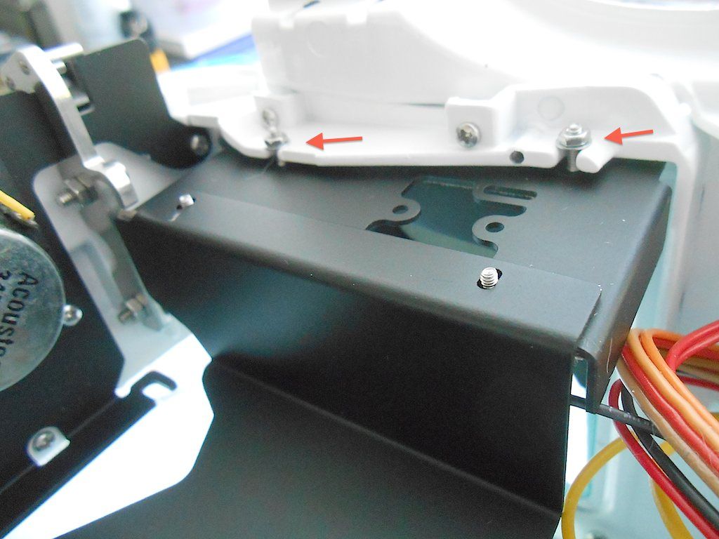 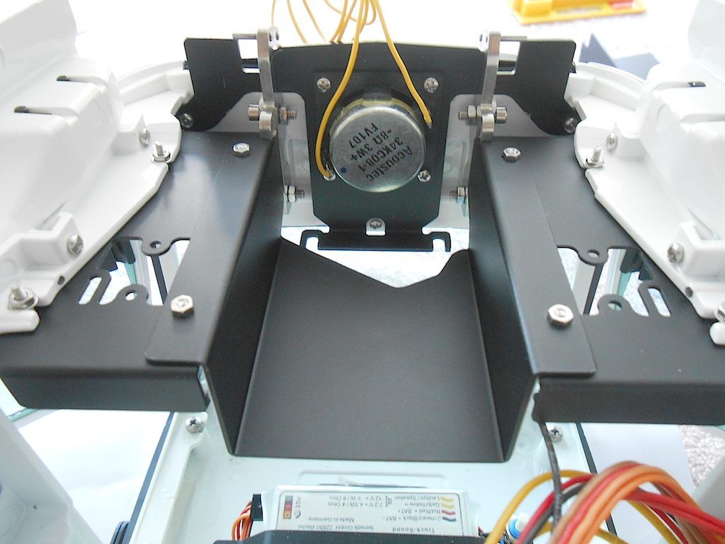 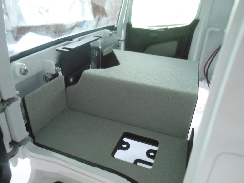 Continued ...
__________________
Cheers, Stephan (Rakthi is the one in the avatar) |
|
#111
|
||||
|
||||
|
Now have to do the back ledge of the interior.
For this we first need to attach the circuit board for the wiring in the cabin. This will make it possible to remove the cabine with only one plug to disconnect. 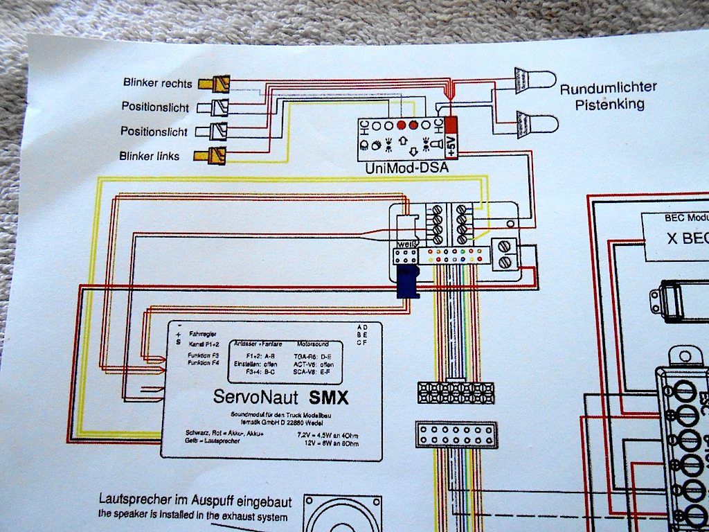 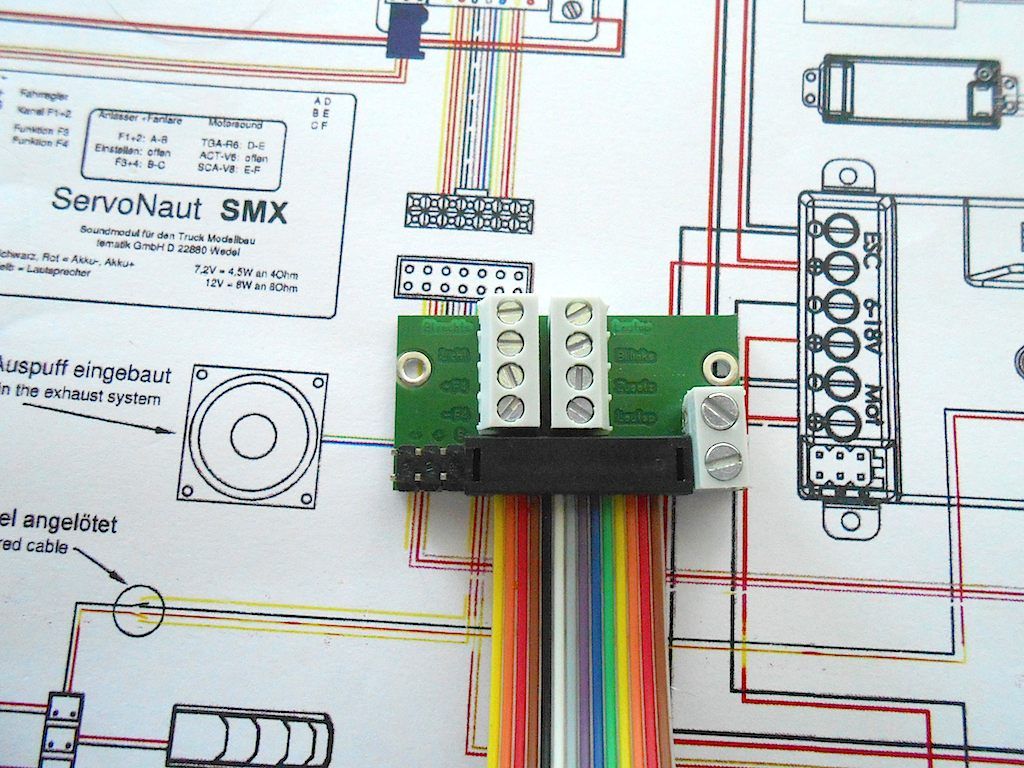 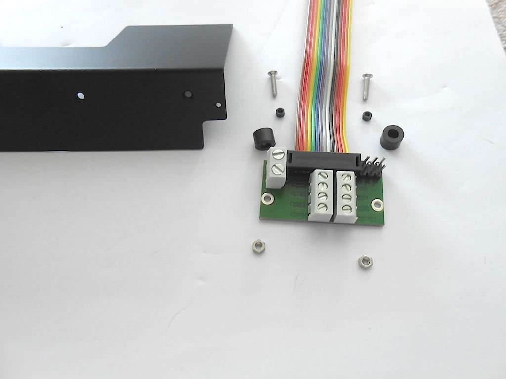 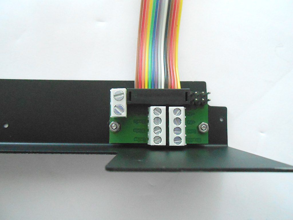 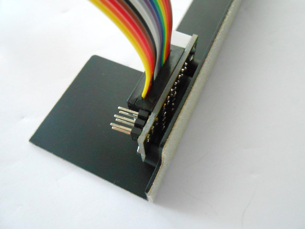 However ... connecting all those cables with the board attached will be a pain. So removed it for the duration. It can be attached again later. 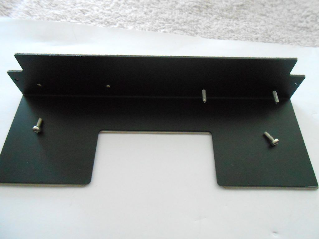 The backboard goes in through the doors and I was surprised how easy it slipped in place. Had expected worse. 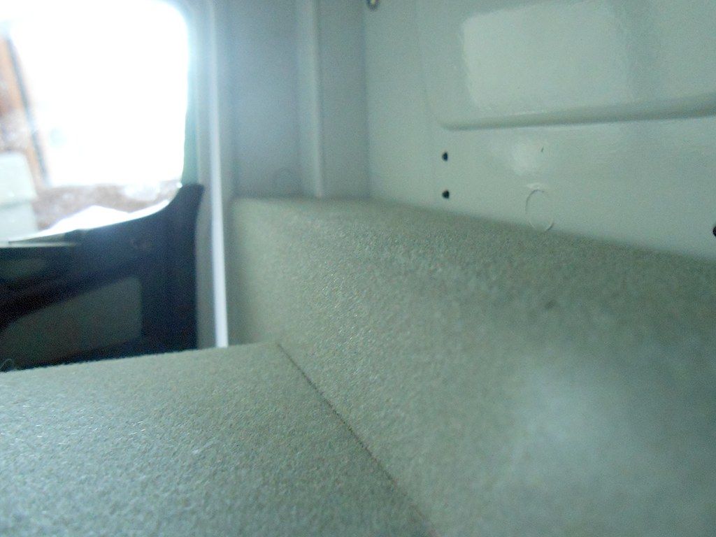 It screws in from the bottom. The hole in the plate is threaded. 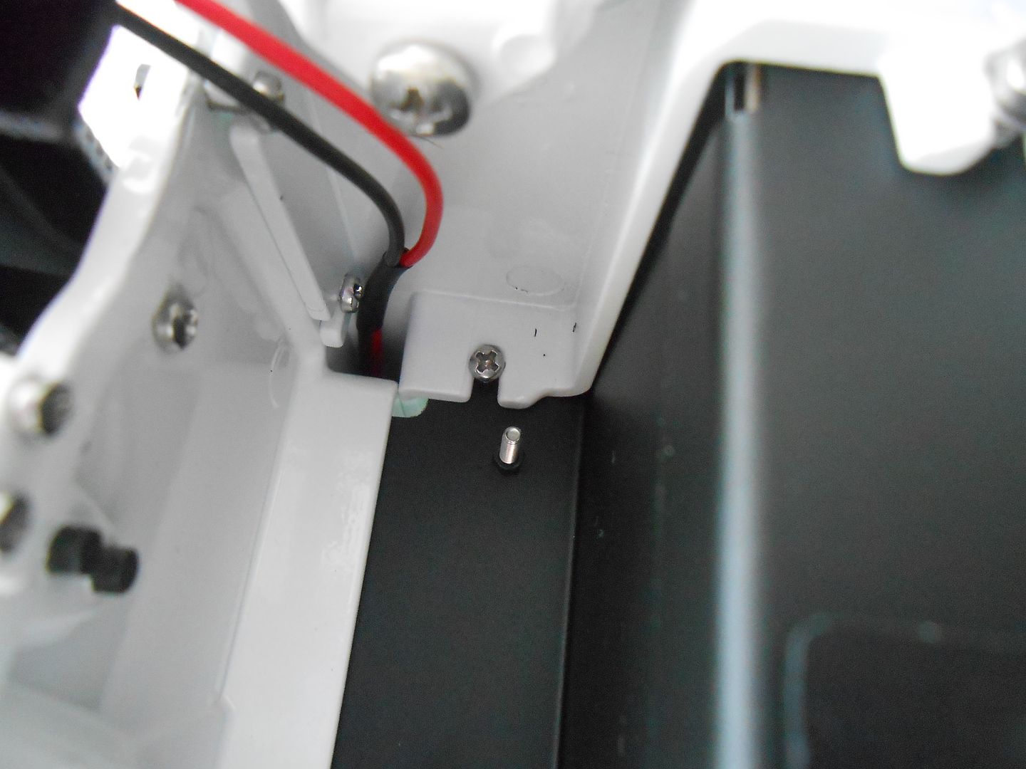 The manual specs M2x6 ... however this makes the screw poke into the cabin with a mm or 2. Replaced those screws with M2x4s left over for another group. Perfectly flush now. 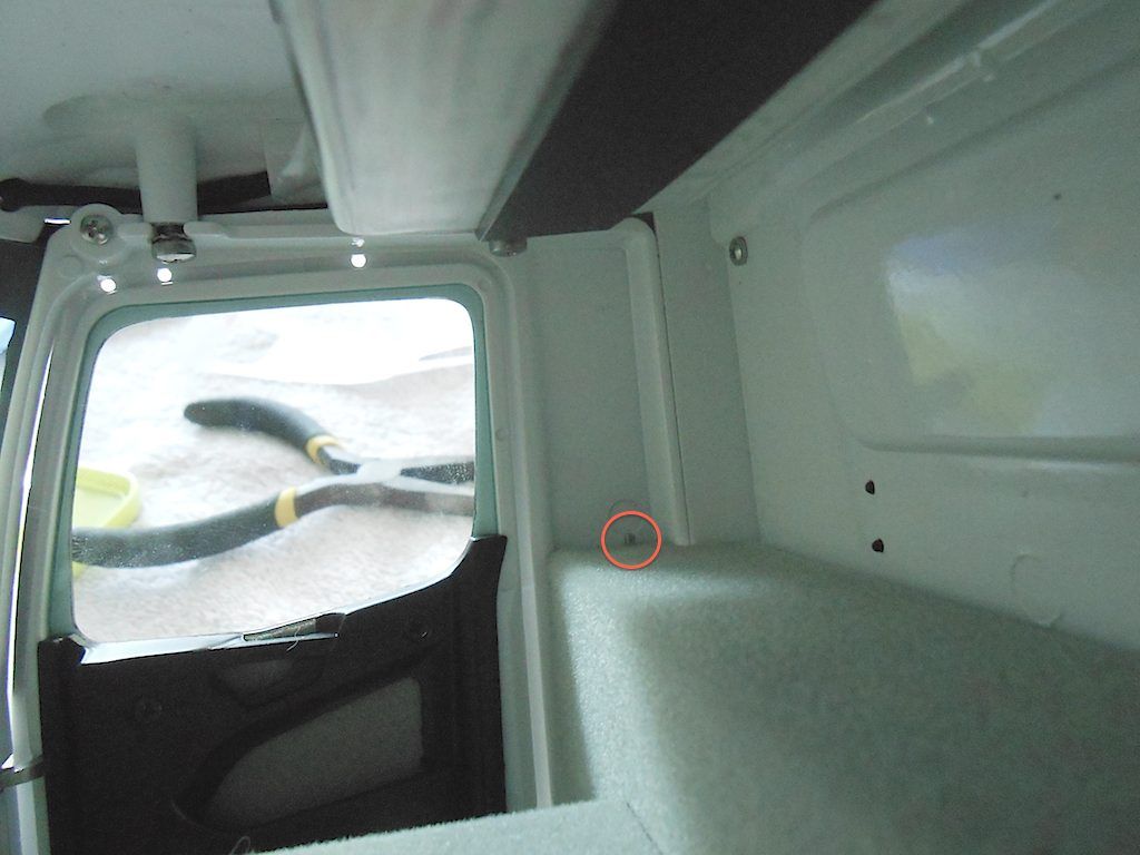 Noticed I had forgotten the seat bases. Supposed to be bolted on before installing the floor. Still easily done good access from below. 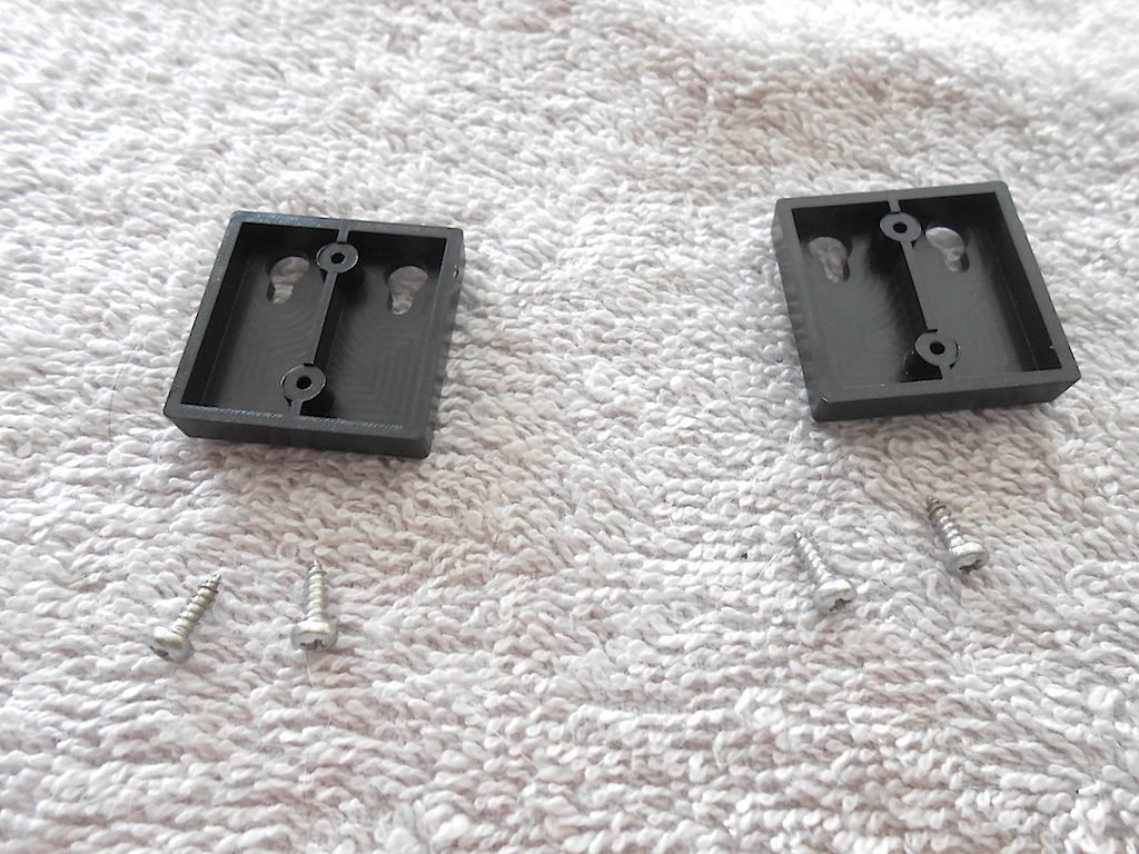 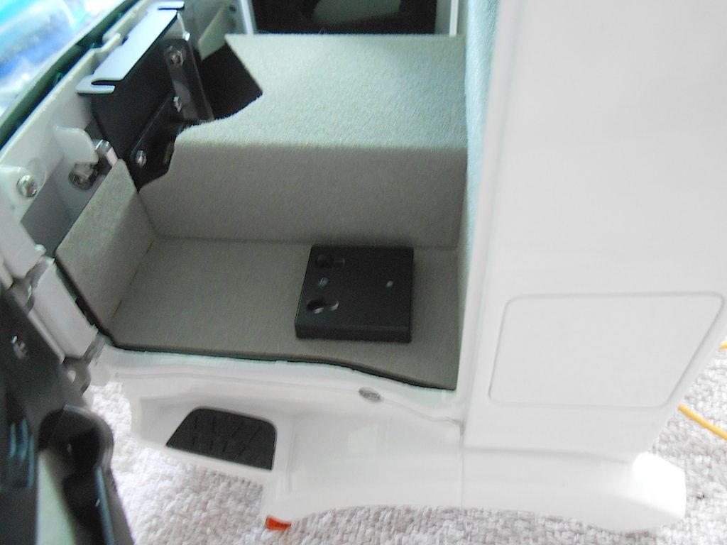 Next up the seats and dashboard or maybe I do the cabling first ... (so not looking forward to that bit) Cheers Stephhan
__________________
Cheers, Stephan (Rakthi is the one in the avatar) |
|
#112
|
||||
|
||||
|
No point postponing jobs you don't like ... since nothing much going on today, bit the bullet and messed with the electrics of the cabin.
Sod's luck of course ... the bleeding power cables of the SMX are ½ inch too short ... 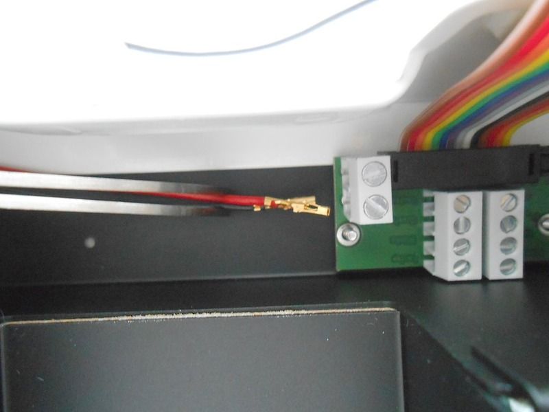 Inserted the LED for the indicators and attached them with a blob of hot glue. Kind of regret it, I made an error and when removing the glue, part of the paint came with it. (right side). Well one can't see it, and thinking of painting the underside of the fender black anyway like in real life, so no big loss. 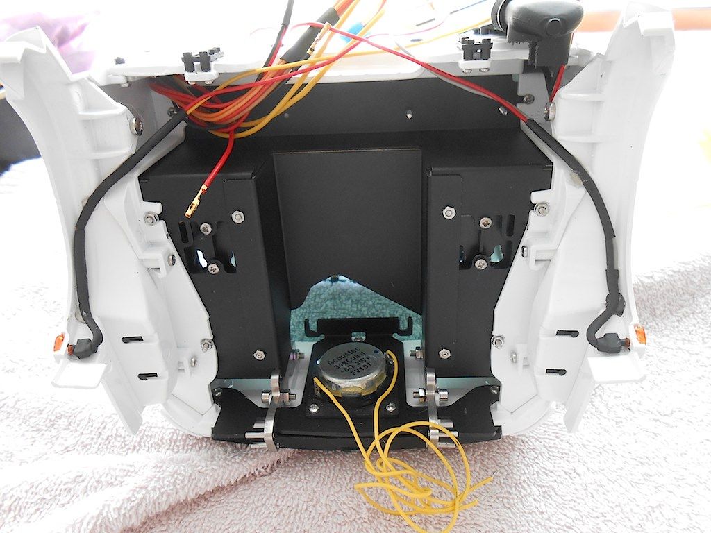 Globbed some liquid tape on the back of the circuit board. Not really needed, but better safe than sorry with electricals. 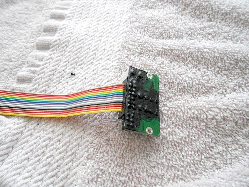 Inserted the 2 plugs and the Function 4 cable of the SMX plug. Since the speaker stays in the cab, I could actually just have soldered the wires together instead of making this convoluted connection.  oh well ... The speaker cables from the SMX were too thick to go into the provided holes. oh well ... The speaker cables from the SMX were too thick to go into the provided holes.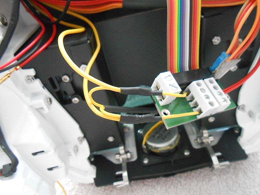 Rummaged through the bits and pieces one accumulates and found a female JST (?) plug that fitted the power of the SMX Module. Came with one of my chargers, but never used it. Also fitted the Universal Bus thing to the circuit board. I could have run that one separately to the bus connectors in the lower level, but then one extra plug to undo. 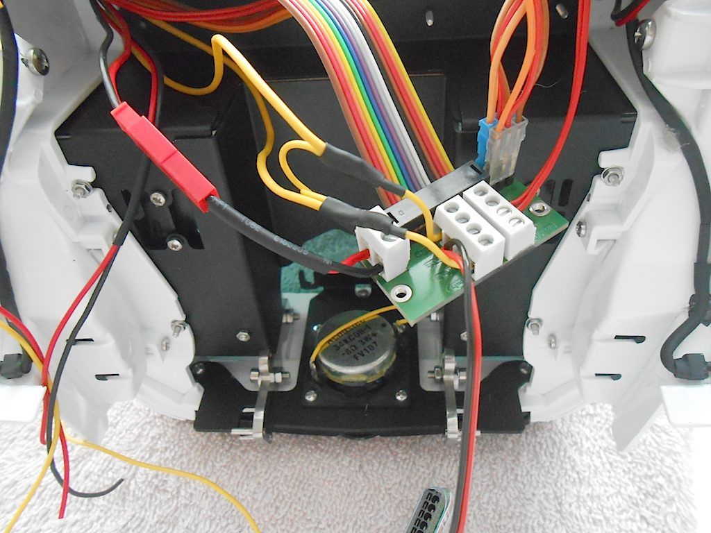 Bolt the circuit board in place, which went easier than I expected. 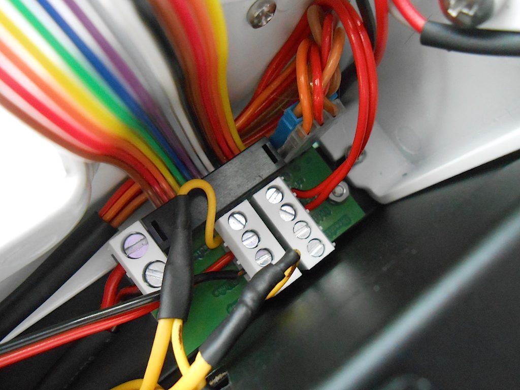 And now to deal with the KingBus system. The wires need be coated in some solder to make them stiffer, and then you can push them in the round hole where they clip in. To release them put a thin screwdriver in the rectangular slot and push down. (I didn't know this) 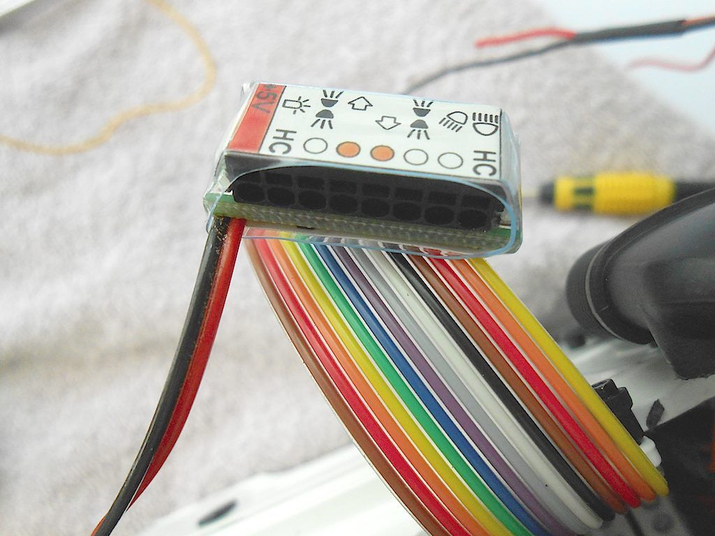 All good an well for the single or double cables, but the 4 positive ones ... so I soldered them together and filed them to a reasonably small pin. (sorry shoddy pic but you get the idea) I know there are probably connectors in which you put the cables etc etc ... Wish I knew how they were called and where to get them. 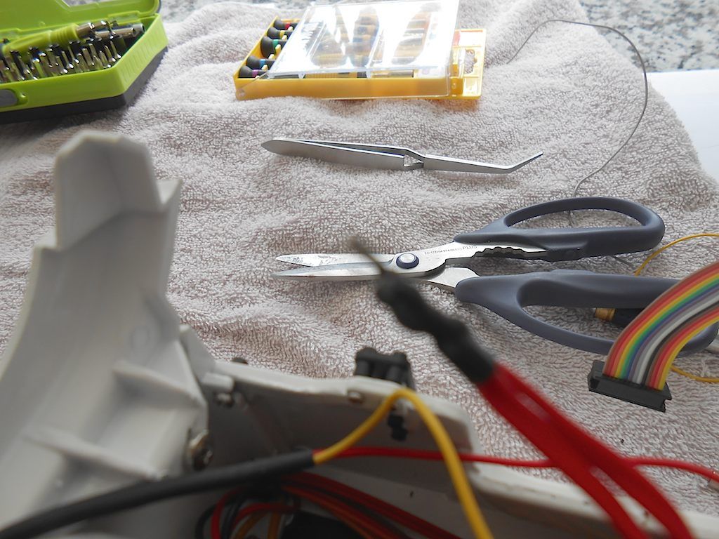 All the cables inserted in the module 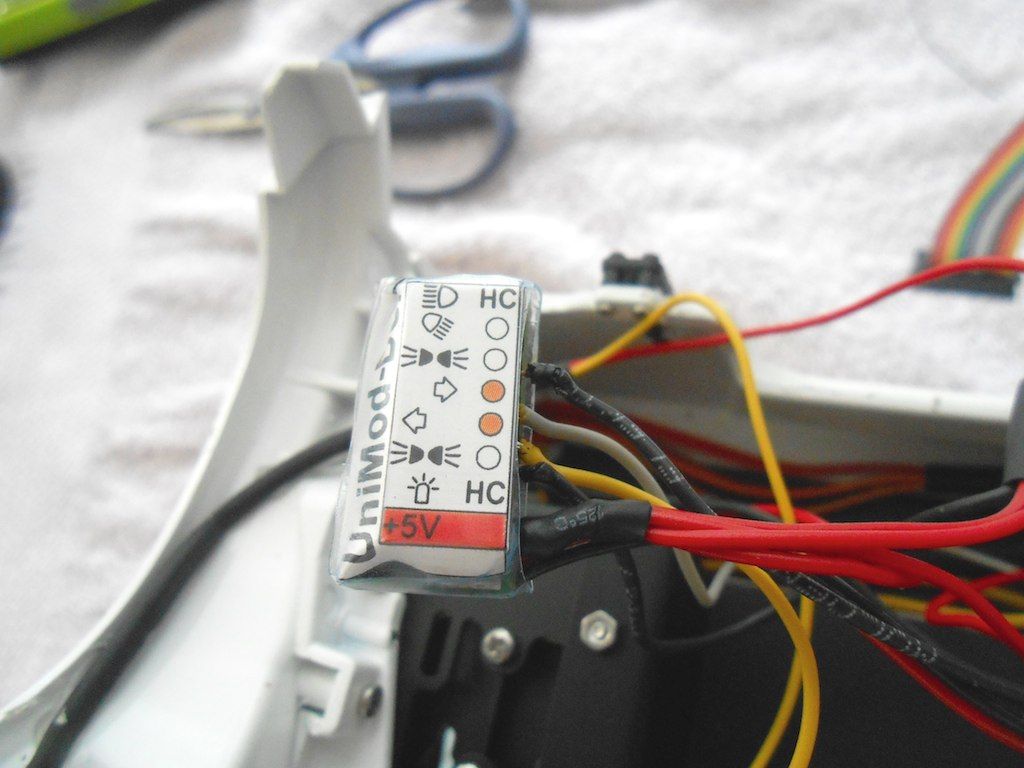 Module glued to the side of the cabine with the provided double sided tape. 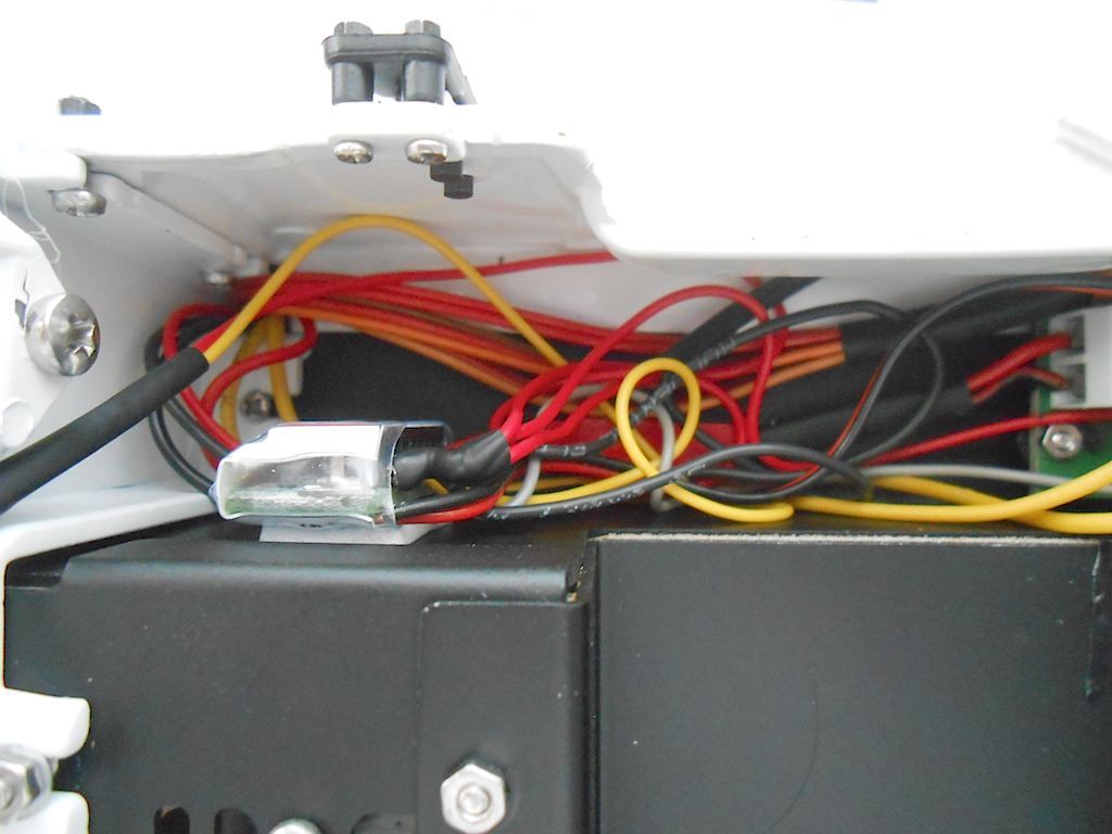 And a view of the mess ... left all cables long enough so I can be redone if needed. Thinking of cutting some foam to hide it from sight. 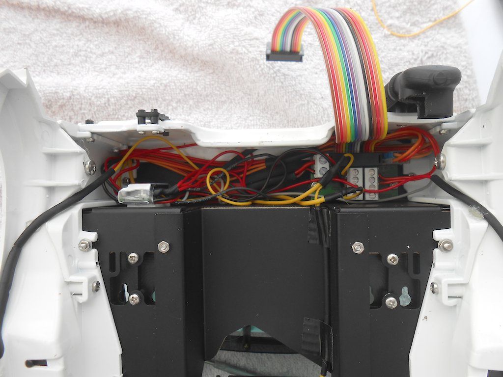 So all in all this little exercise kept me busy for 3 hours + ... and I don't know if it is correct until I sort out the rest of the electric. Cheers! Stephan
__________________
Cheers, Stephan (Rakthi is the one in the avatar) |
|
#113
|
|||
|
|||
|
Thank you for posting all the pictures of the build. It must have taken as much time to do as it did to build the kit.
Ken O |
|
#114
|
||||
|
||||
|
Hi Ken, taking the pictures doesn't take that much time at all. Just a cheap autofocus camera that is not too good at close-ups. My other one was better but that one became unreliable and started losing pics. This is the third build where I take pics, has become part of the process.
Getting the nuts on some of those screws takes way more time.  Anyway, glad you like it! Best regards! Stephan
__________________
Cheers, Stephan (Rakthi is the one in the avatar) |
|
#115
|
||||
|
||||
|
Finishing of the cabine - Part 1
Started with the seats Left the passenger seat and right the driver's seat. Neatly packaged and best not opened together and parts mixed as there is a definite left and right seat. 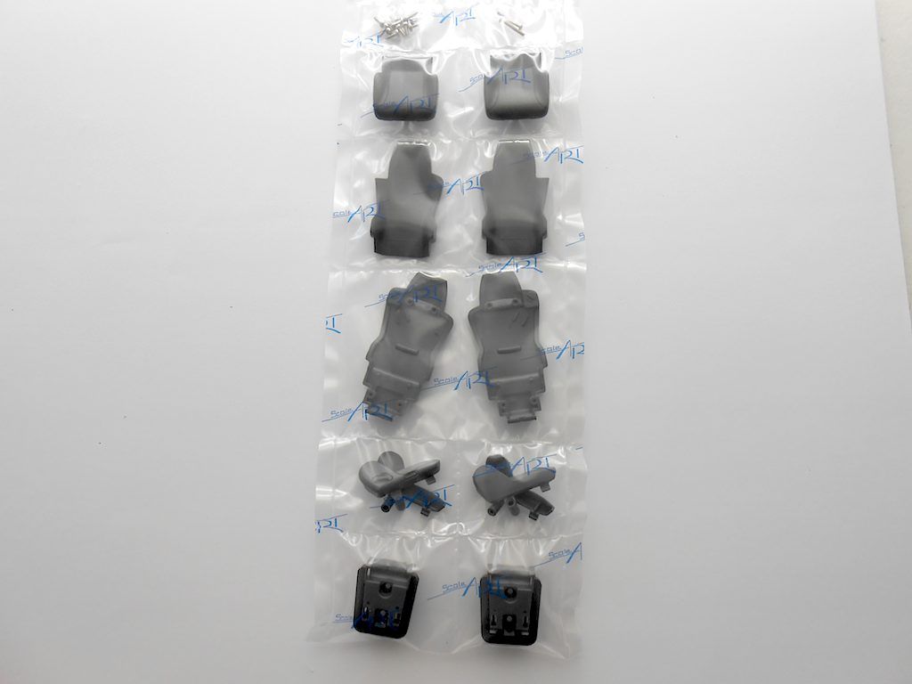 Started with passenger seat 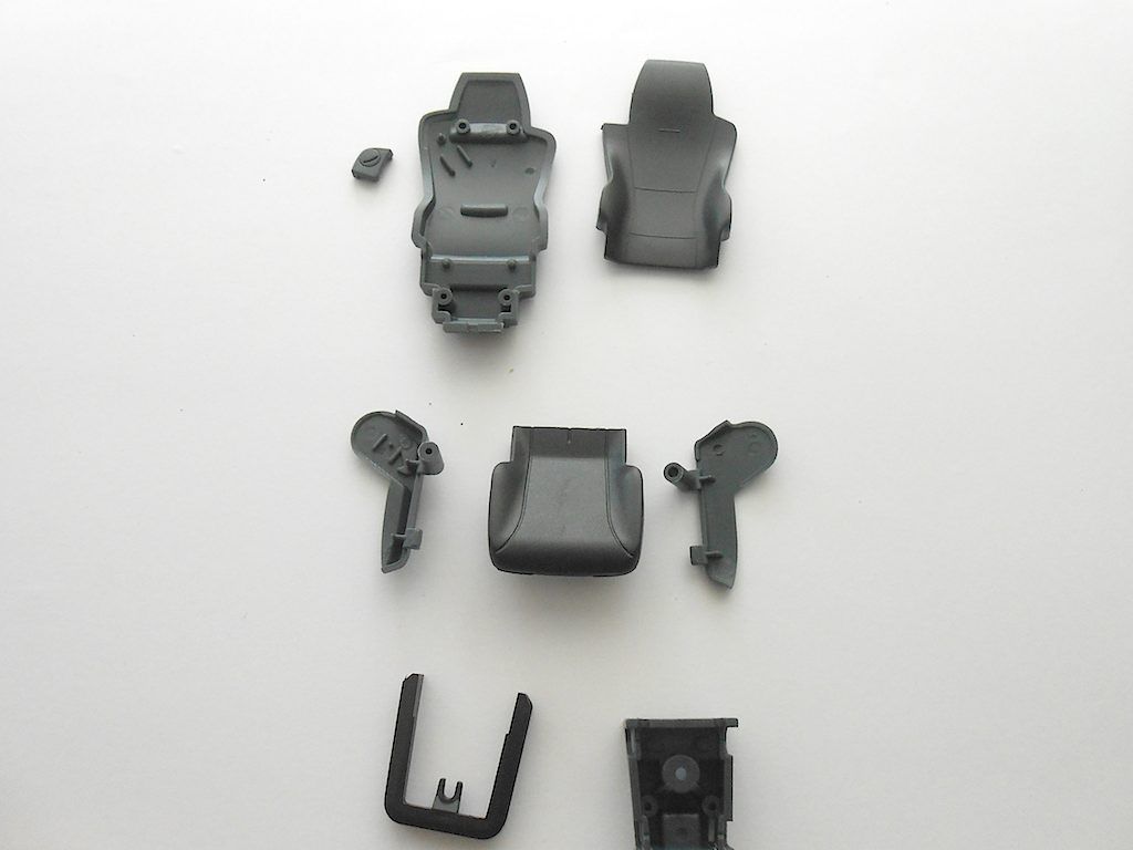 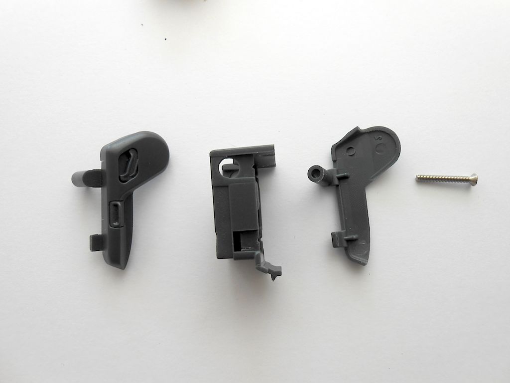 These parts supposed to be glued together with super glue, but after I test fitted them they were solid as can be. So left them as they were. If I ever find the right material I can then make a miniature safety belt like the guys in Germany do.  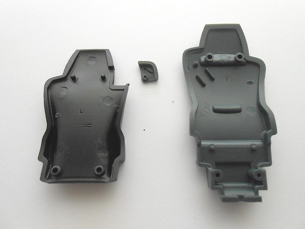 Screws on to base 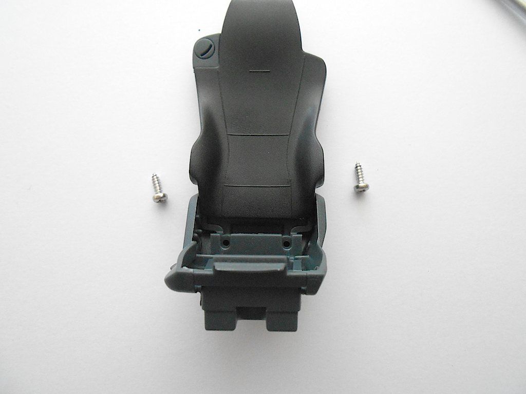 Seat cushion next 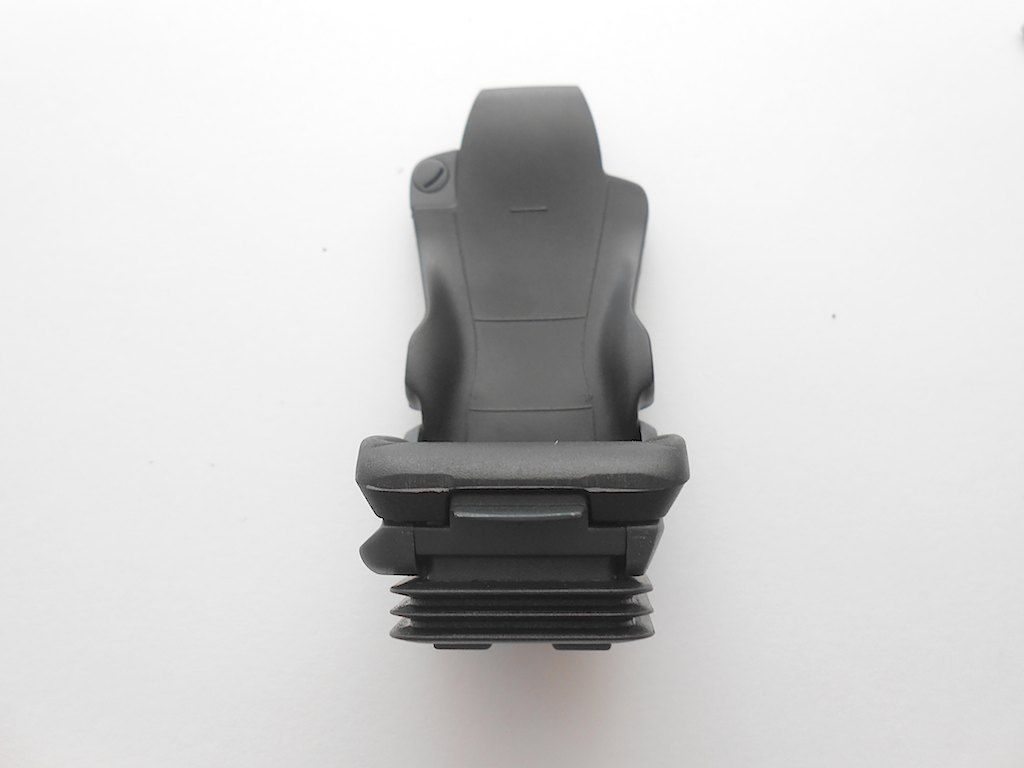 Bolts on from below with the same self tapping screws (one you do not see because I used one of my black ones. 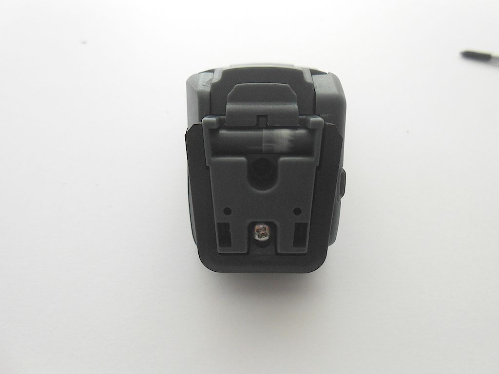 Passenger seat right side 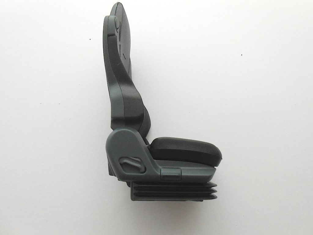 Left side 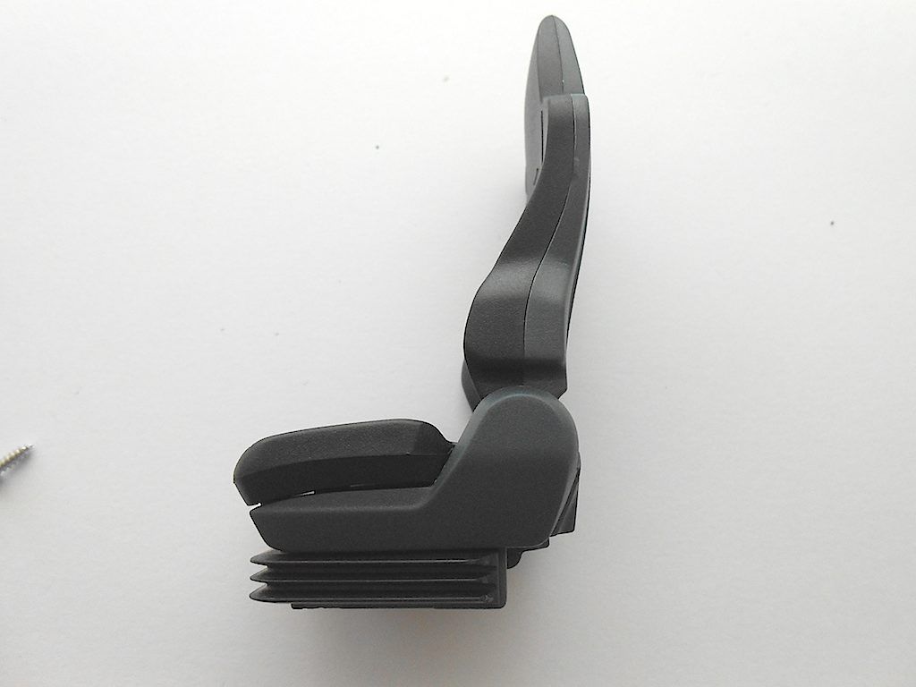 Both finished 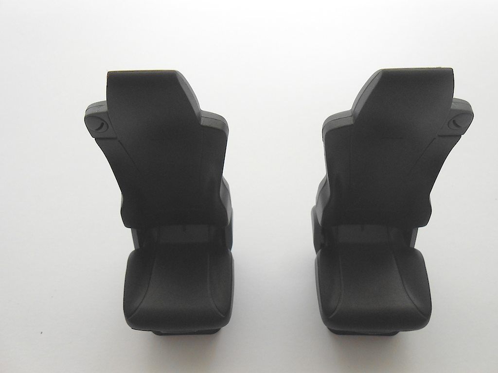 Next steering wheel and steering column The covers get glued on with super glue. 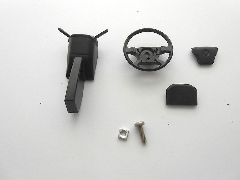 Make sure the square nut is well seated. In this picture it is not right. sits too high and then the cover doesn't fit. 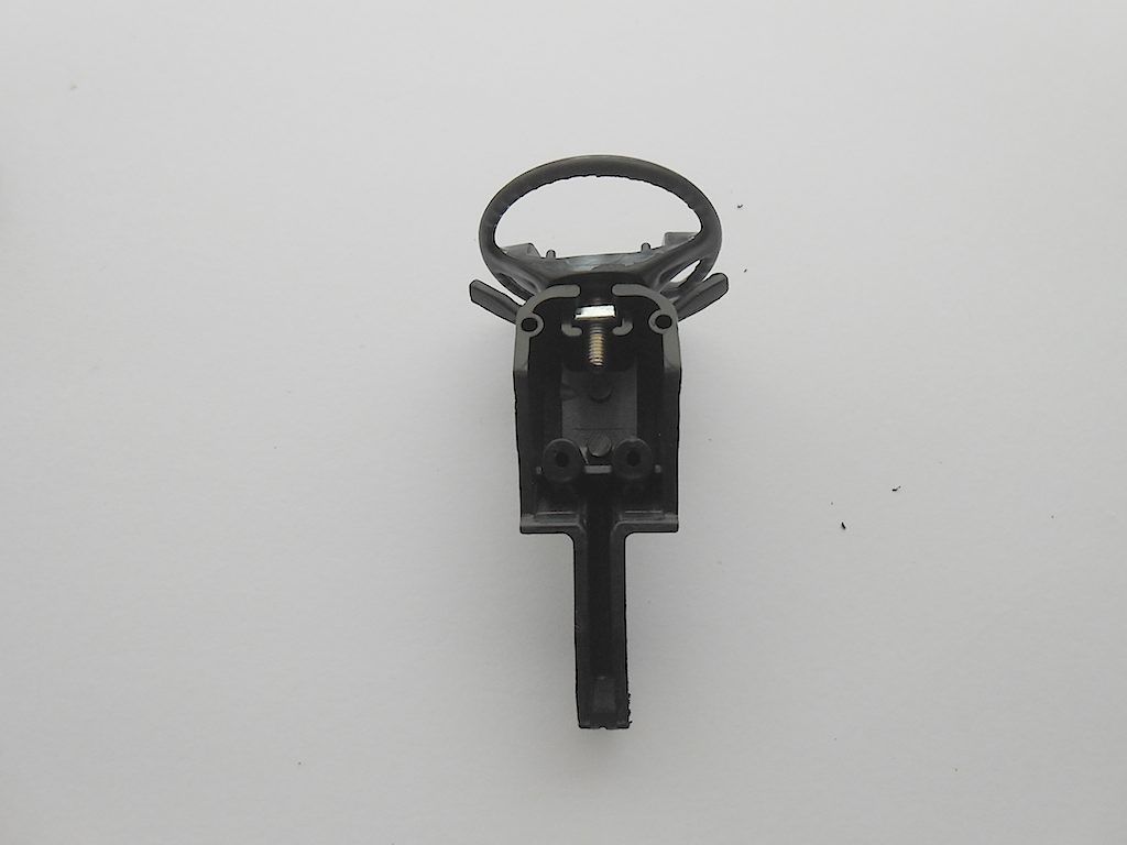 Sticker of instruments stuck to the provided piece of plastic 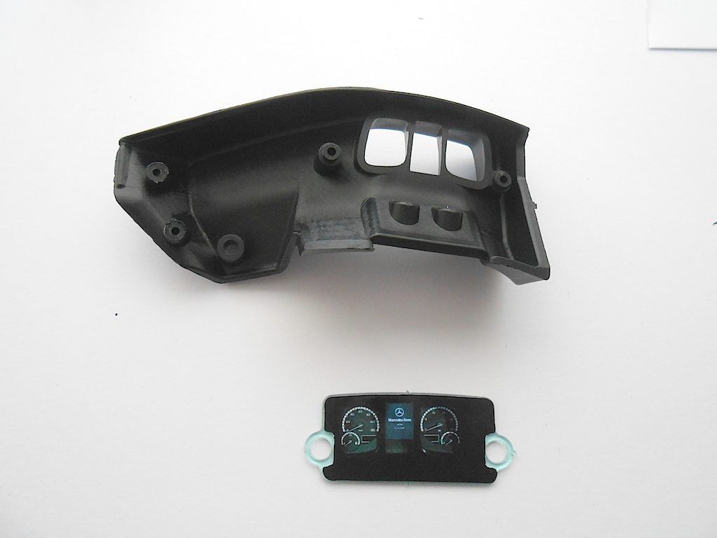 The steering column attached to the driver's side dash with 2 M2x10 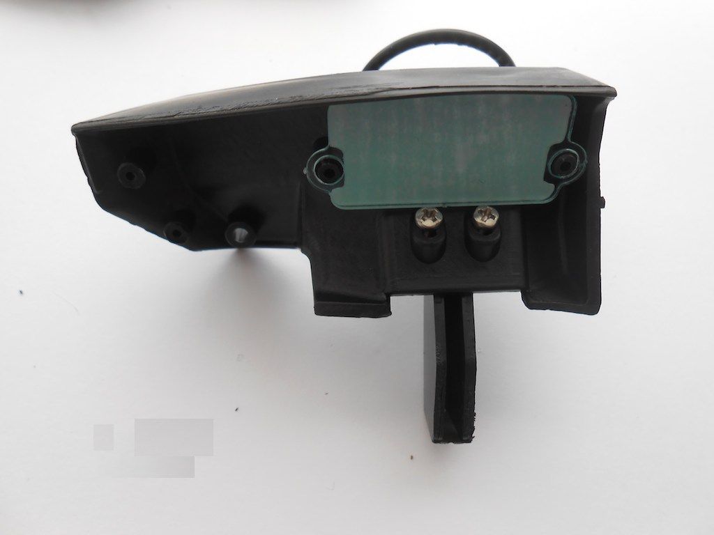 Top of the dashboard and passenger's side. The little part is painted in silver by me. Only part I put some paint on. Don't trust myself to paint the little buttons etc. 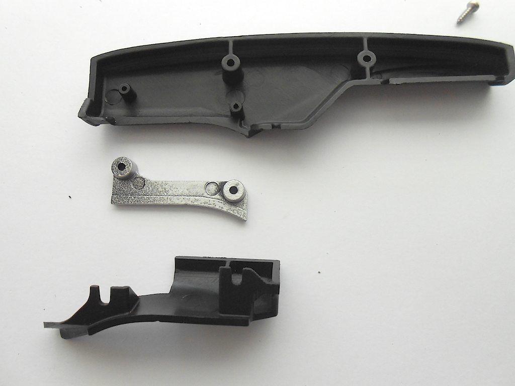
__________________
Cheers, Stephan (Rakthi is the one in the avatar) |
|
#116
|
||||
|
||||
|
Part 2
Other side 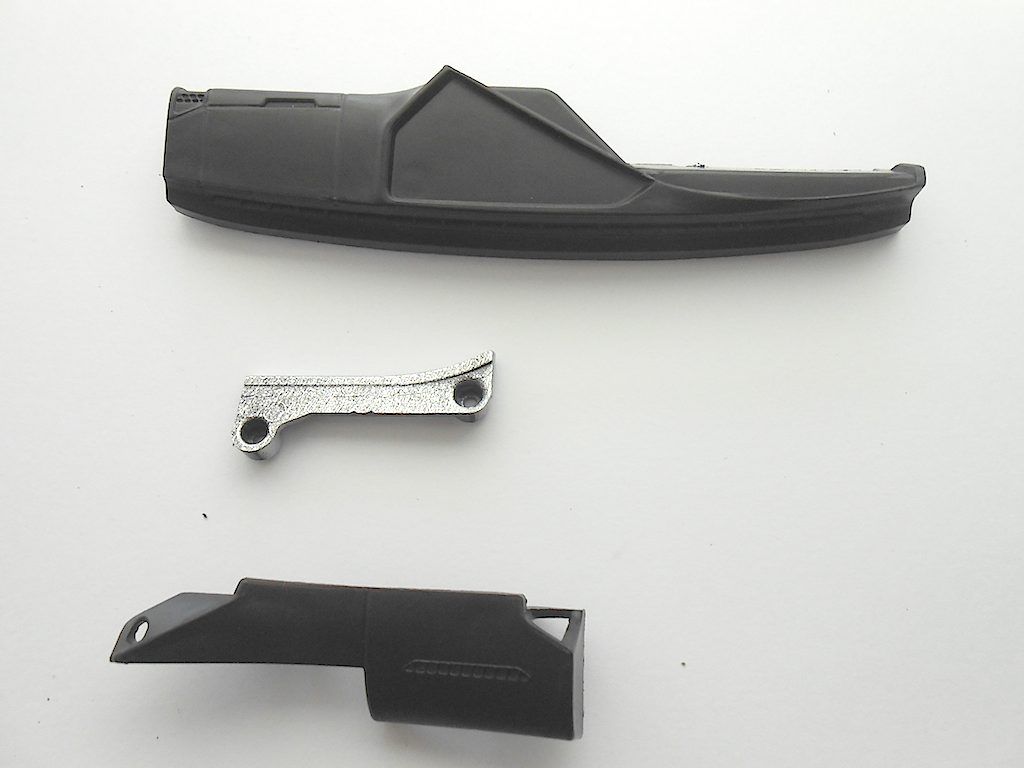 Prepping to put the parts together 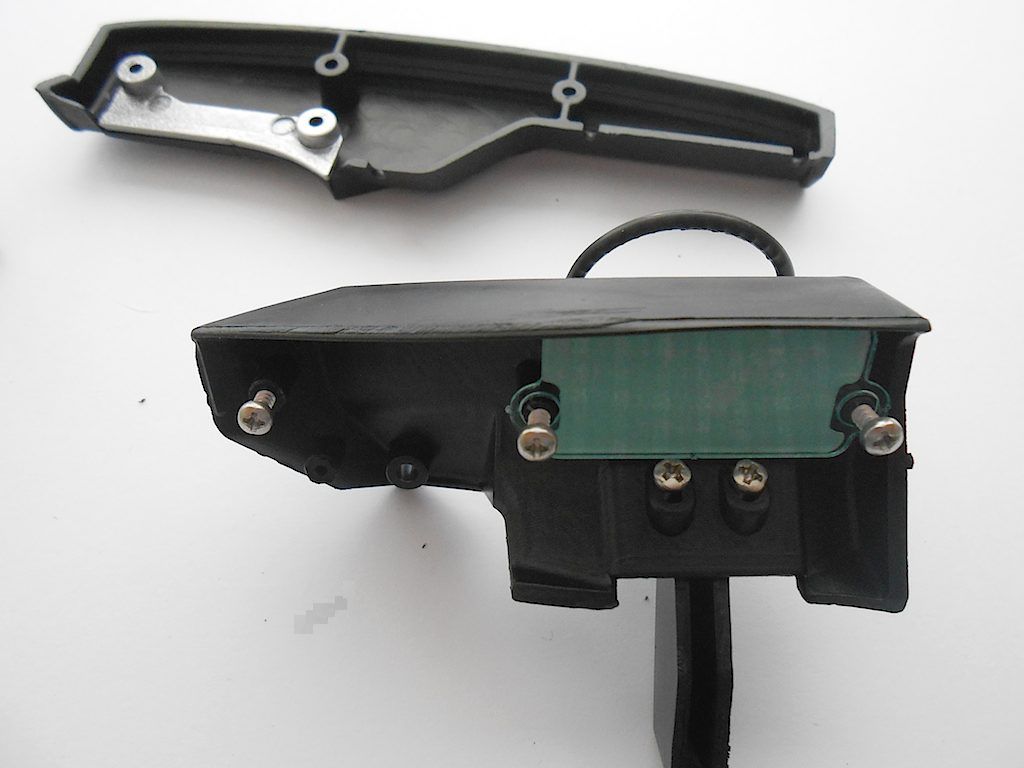 Here missed some pics - got distracted by the cats who caught some critter and let it loose in the house. Missing step is screwing the lower part of the dashboard on. 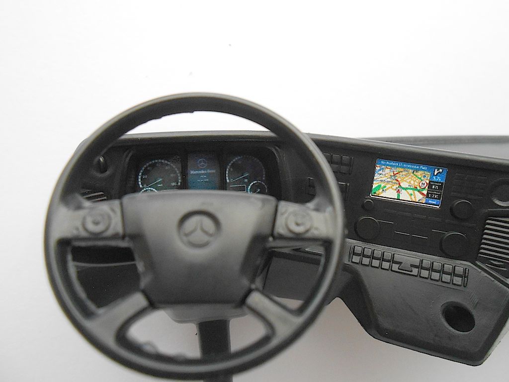 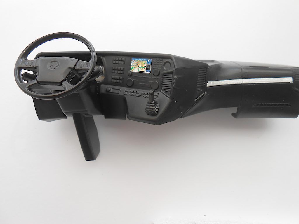 Prep the whole console for installation in the cabin. Gets attached with 2 M3x6. Lazy and just took the ones that were used for painting. 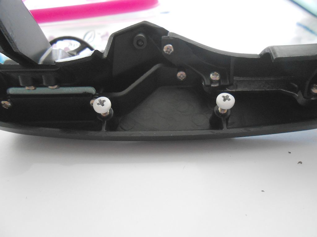 Installed. The left one had to be removed otherwise can not get the console in place. Getting that one screw in is about the most difficult part of this whole job. 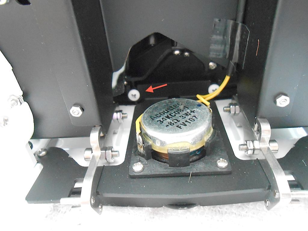 Now the seats go in. Also install screws before inserting in cab. Slots are provided for that in the base 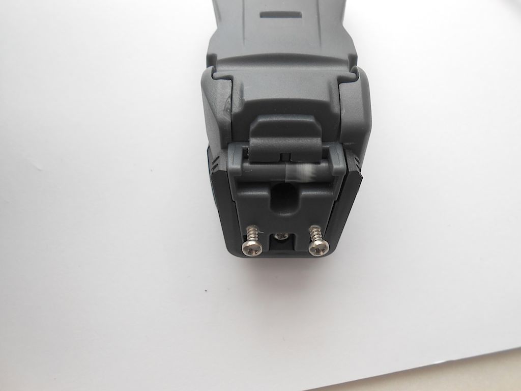 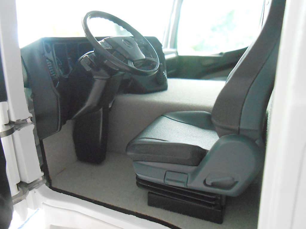 Next is the mirrors and other miscellaneous bits. I didn't take pictures here because it all gets glued together with super glue. Don't like working with it as it sets fast and you can't afford mistakes. Not a difficult job really. Here is picture of the page in the manual 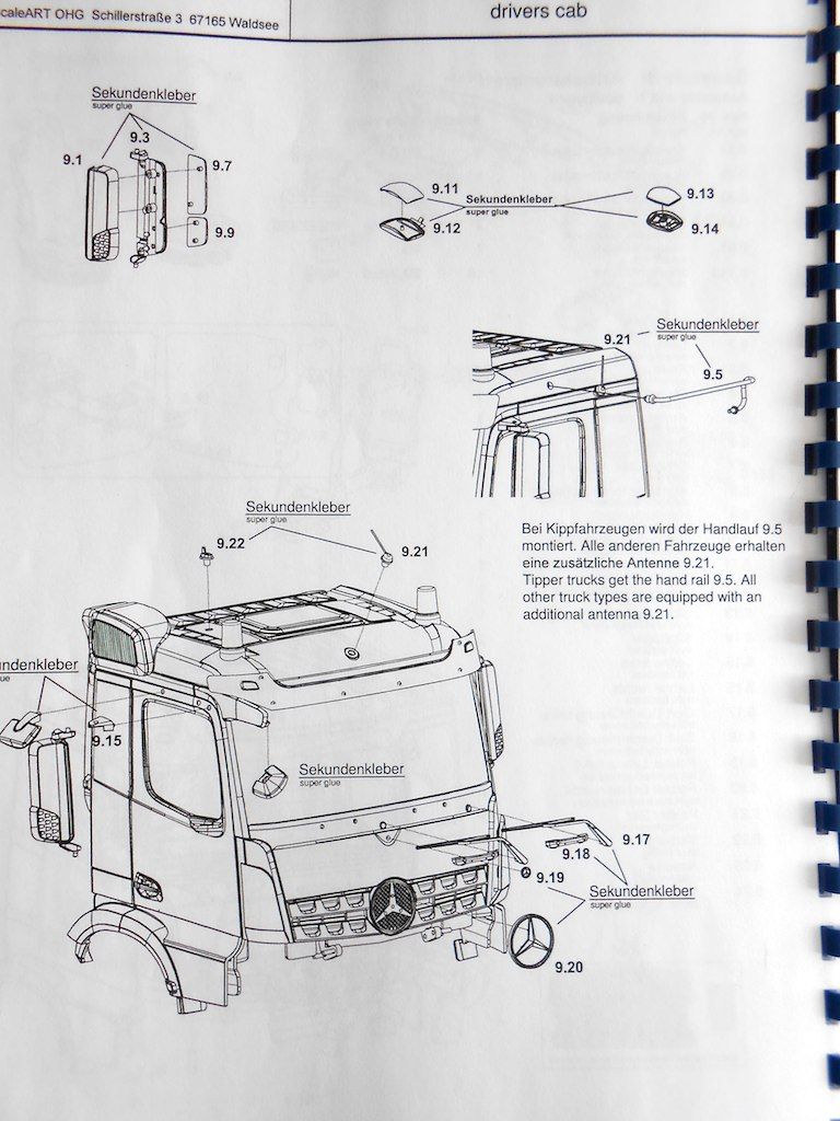 Part of the mirrors were labeled wrong. The bigger part of the main mirror needs swapping L en R. Pic is of the left mirror. The mirrors can be adjusted. 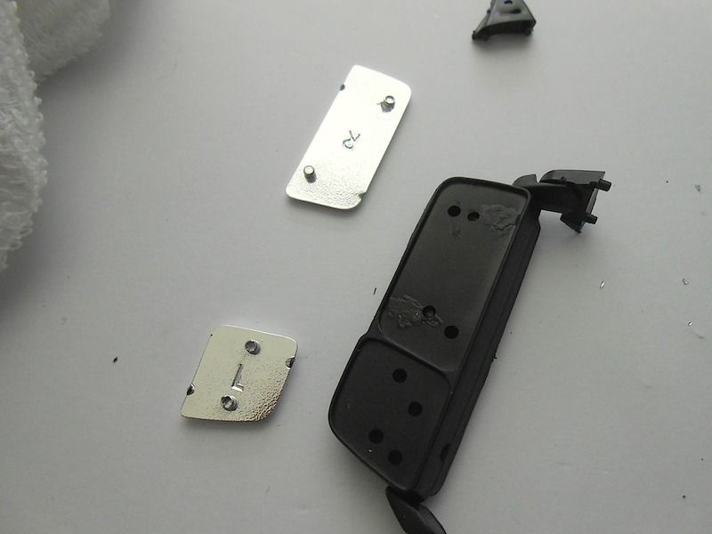 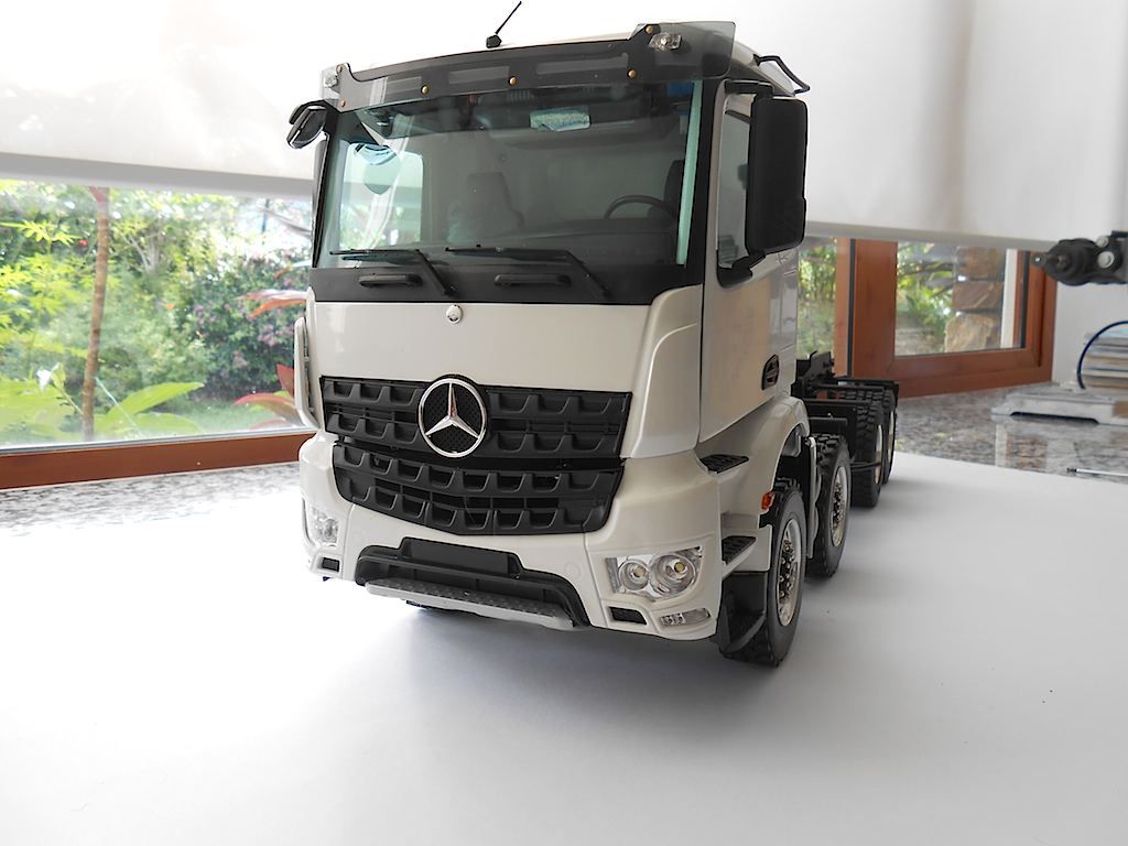 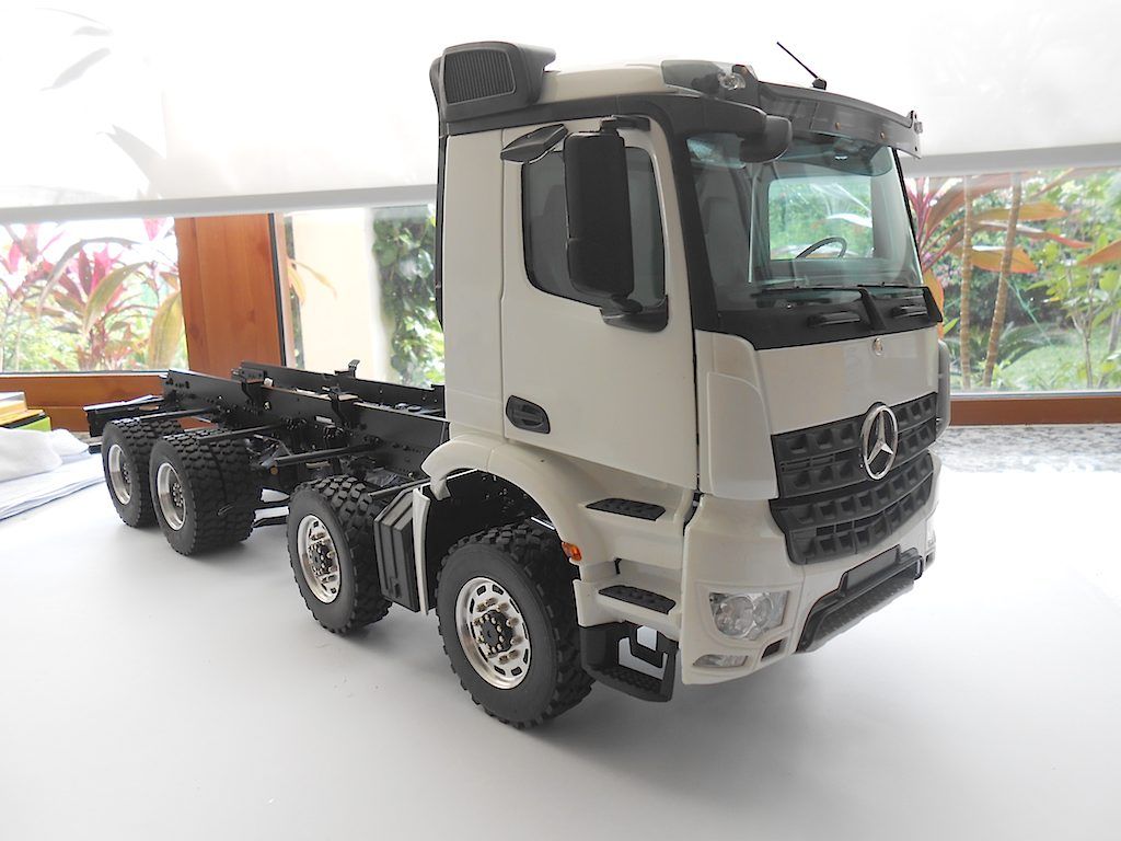 That's the driver's cabin done with. Now back to the more interesting bits which is finishing the hydraulics. Probably start on that later in the week.
__________________
Cheers, Stephan (Rakthi is the one in the avatar) |
|
#117
|
|||
|
|||
|
Looking good!
|
|
#118
|
||||
|
||||
|
Nice colors

__________________
Emil G | MFZ Blocher Fendt 926 | RC4WD Volvo EC480 excavator | Carson LR 634 | Kenworth 6x6 hauler | Kenworth 6x6 dtrk My channel: To view links or images in signatures your post count must be 10 or greater. You currently have 0 posts. Construction site on Facebook: To view links or images in signatures your post count must be 10 or greater. You currently have 0 posts. Pictures on Instagram: To view links or images in signatures your post count must be 10 or greater. You currently have 0 posts. |
|
#119
|
||||
|
||||
|
looks great as a rolling chassis without the roll on/off equipment fitted
|
|
#120
|
||||
|
||||
|
Amazing build so many screws
 keep up the great work |
 |
| Tags |
| 8x8, arocs, scaleart |
| Currently Active Users Viewing This Thread: 3 (0 members and 3 guests) | |
|
|