|
|||||||
| Highway Trucks and Trailers On road trucks and trailers single and twin axle trucks. |
 |
|
|
Thread Tools | Display Modes |
|
|
|
#1
 08-30-2021, 03:54 PM
|
|||
|
|||
|
Good point.. you got to know your toys limitations.... people forget that sometimes...
I've looked at the files for this on Thingiverse but haven't done anything with them yet.... Conversions are fun when you take a static toy and make it work.... 
|
|
#2
08-31-2021, 02:00 PM
|
|||
|
|||
|
Bruder Piggyback Forklift Build part 2
I had to wait for a bunch of the parts I needed for this build to arrive so decided to start by making and installing the rear drive and steering assembly. This assembly requires printing out the 'UPS_drive_motor_arm' and 'UPS_steering_mount_V2' parts from the Thingiverse files. In this posting I am just going to cover the installation of the steering mount. This photo shows the steering mount and battery cover on the 3D printer build plate. [img] 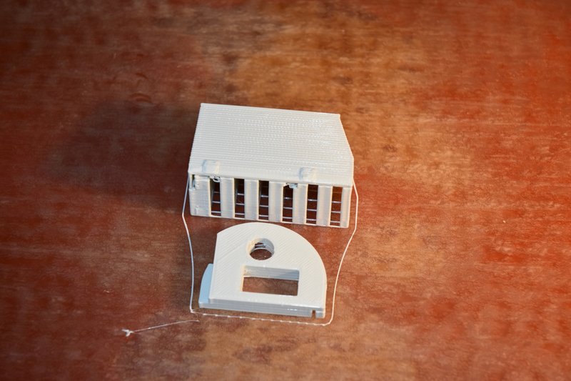 [/img] [/img]You will note that the steering mount is not symmetrical and the slot for the servo is not centered. How to install this part and keep the servo axis centered in the forklifts wheel well? Here's how I did it. The mount is designed to use a standard 9gr micro servo that is inserted into it's mounting slot from the bottom. You could just install the servo and eyeball the placement but I wanted to ensure that it was dead center. This photo shows the parts I used. [img] 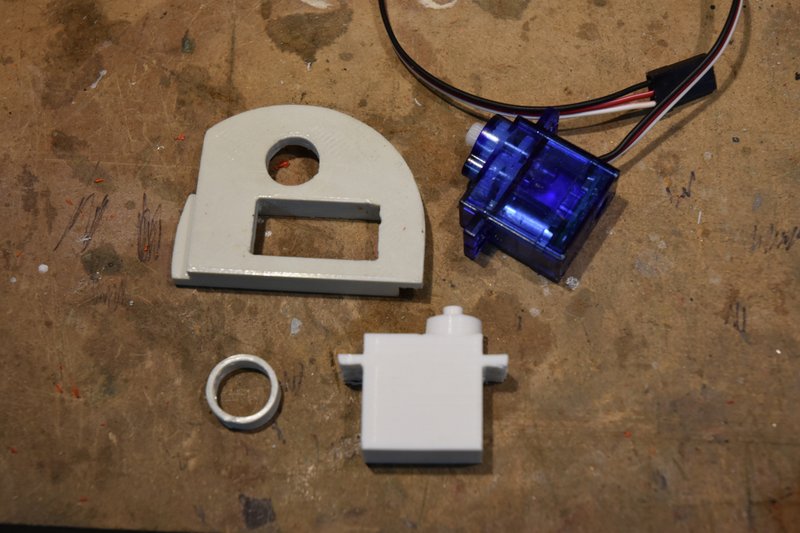 [/img] [/img]At the top is the steering mount and a micro servo. In the bottom is a 3D printed copy of the servo and a ring. You don't need the servo copy but I already had some left over from another project where they were used to help design the layout of hydraulic components. Using the copy servo kept dangling wires out of the way. The ring was sized to take up the difference in size between the steering mount hole in the back of the lift and the neck of the servo. The ring, servo and steering mount were put together and then placed over the hole in the back of the lift. [img] 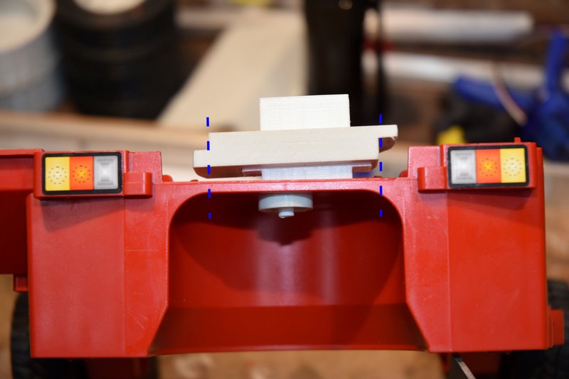 [/img] [/img]This ensured the axis of the servo was centered in the wheel well. Using a straight edge I then transferred the location of the steering mount sides down to the lift body. I then used a small square to draw out the straight cut lines on the floor of the lift. [img] 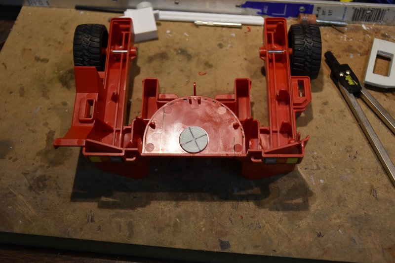 [/img] [/img]Next I printed a plug sized to fit in the hole of the lift with a center mark drilled in it. This is used to hold one arm of a pair of dividers or a compass set to match the radius of the curved part of the steering mount. The divider or compass can then be used to scribe the curve that needs to be cut out. This next photo shows the resulting guide lines for the cuts that need to be made. [img] 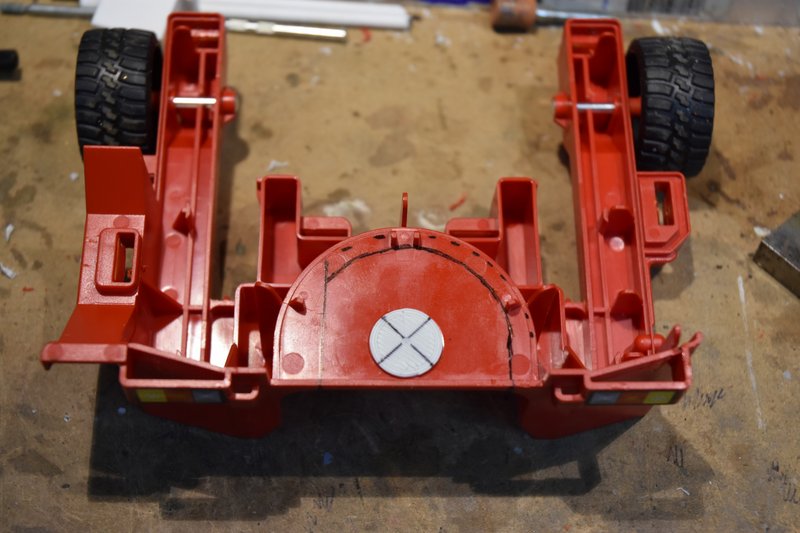 [/img] [/img]The base is then cut out using whatever method you prefer. I used a short Xacto saw blade on the straight cuts and a length of thread to cut out the curved portion. [img] 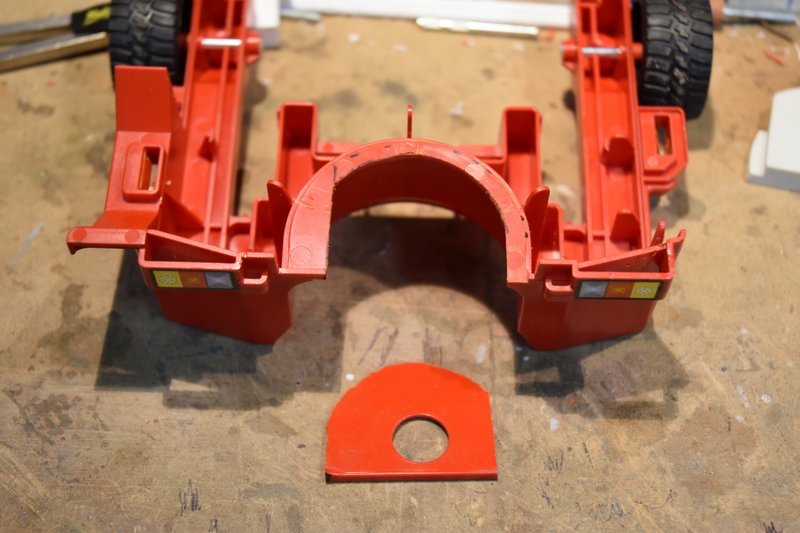 [/img] [/img]The printed steering mount can now be glued in postion as shown below. I used a two part epoxy. [img] 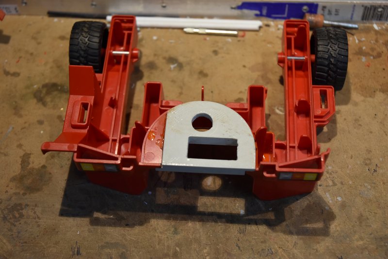 [/img] [/img]The reason the curved part of the mount is on top of the floor and the straight part is underneath is because there is a portion of the top half of the lift that hangs down and when installed will almost touch the floor just to the left of the mount. More about this later on. After letting the epoxy cure fully, I installed the servo and then placed the upper half of the model in place to check on fit. As can be seen in the next photo the thickness of the mount is thicker than the floor section removed was and will not allow the two halves to come fully together. [img] 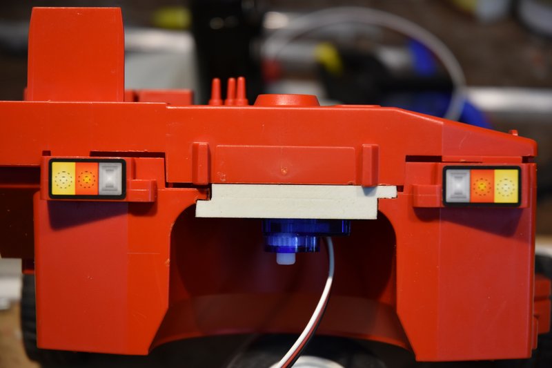 [/img] [/img]Simple fix, just mark on the upper half where the edges of the mount hit and then cut/file/sand a notch just deep enough that the two halves will come fully together. [img] 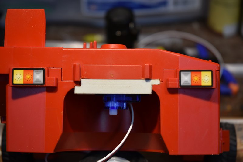 [/img] [/img]That left a nice big gaping hole in the top of the lift where the manual knob used to be. [img] 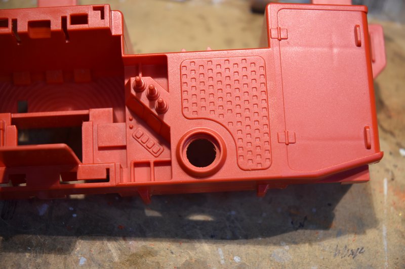 [/img] [/img]Again, a fairly simple fix. Measure the diameter, transfer to a flat piece of styrene and cut out a disc to glue in place over the hole. [img] 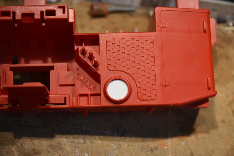 [/img] [/img]And then file and sand the rim down flush with the disc. [img] 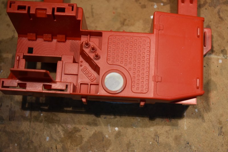 [/img] [/img]Just having that plain flat disk there kind of bothered me after looking at it for awhile. On a real lift why would it be there? Well maybe we can make it look like an access plate for maintenance. I used to be heavy into model railroading years ago and still have a lot of modeling parts for rail cars left over (never throw anything away, right). Looking through that stash I came across some nut/bolt castings that I thought would dress up that plate and make it look like it could be removed. Measured the outside diameter of the plate rim and printed up a disc with evenly space holes to use a a drilling template. [img] 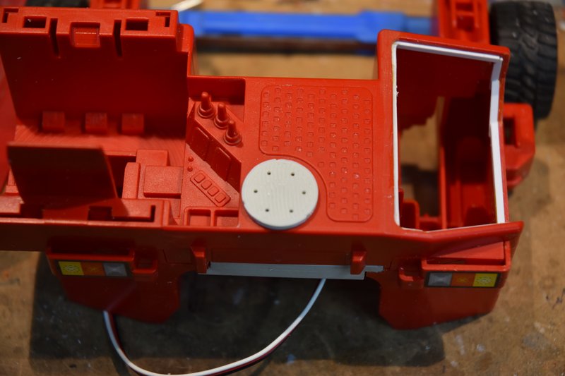 [/img] [/img]Drilled holes of the proper diameter to match the castings. Inserted the nut/bolt casting into place and glued from the backside with CA. They are square headed nuts but they are so small that its not really noticeable and I think made a big difference in the appearance of the model. [img] 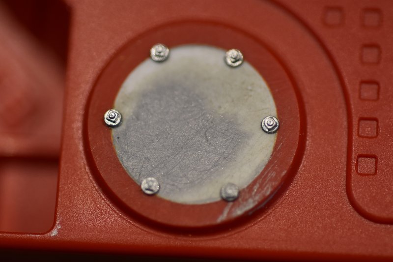 [/img] [/img]That's all for this post. I the next one I'll cover the drive motor assembly and installation. Last edited by Zabco; 09-02-2021 at 02:52 PM. Reason: Out of sequence
|
|
#3
09-01-2021, 01:02 PM
|
|||
|
|||
|
Bruder Piggyback Forklift Build part 3
In this part I'll show how I assembled the steering and drive motor assembly. I used a common N20 motor/gear box. The one I used was rated 12V and 100rpm. I used a 12V rated motor because I initially was going to use a 3S LIPO battery and ESC. If you haven't already you need to print out the 'UPS_drive_motor_arm' from the Thingiverse files. The N20 motor was a perfect friction fit in mine and required nothing else to hold it in place. Sorry, don't have a photo just showing how the motor fits into the arm but it's pretty obvious once you see the part. There is a recess in the top of the arm that fits over the shaft of the servo and a standard servo arm screw is used to secure it in place. I had a problem with the arm slipping on the servo and not staying in place. To fix this I put the arm in my small milling machine and cut a flat bottom hole with a 1/4in cutter. [img] 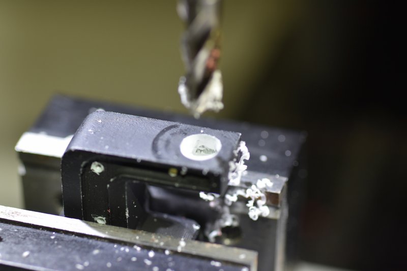 [/img] [/img]I then took an old, damaged servo arm I had and cut the center splined hub out and epoxied it into the hole I just milled. [img] 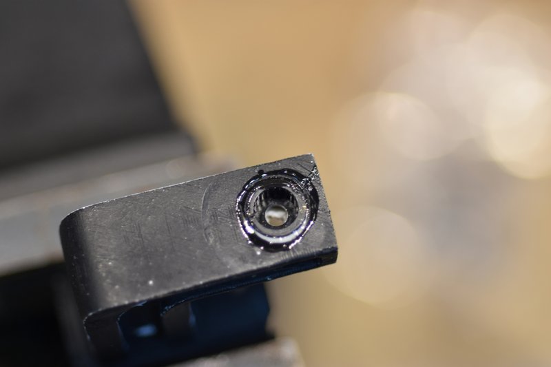 [/img] [/img]This locks the arm to the servo shaft and no more slipping. Next was to mount the wheel/tire to the motor shaft. The shaft from the gear box is 3mm in diameter and is a loose slip fit into the hole in the hub of the wheel. The hub though is longer than the motor shaft so that when placed on the drive shaft the tire is not centered under the servo shaft. To fix this the hub has to be shortened. To determine how much to remove I took a thin piece of plastic, placed it alongside the motor shaft and marked it to use a length gauge. [img] 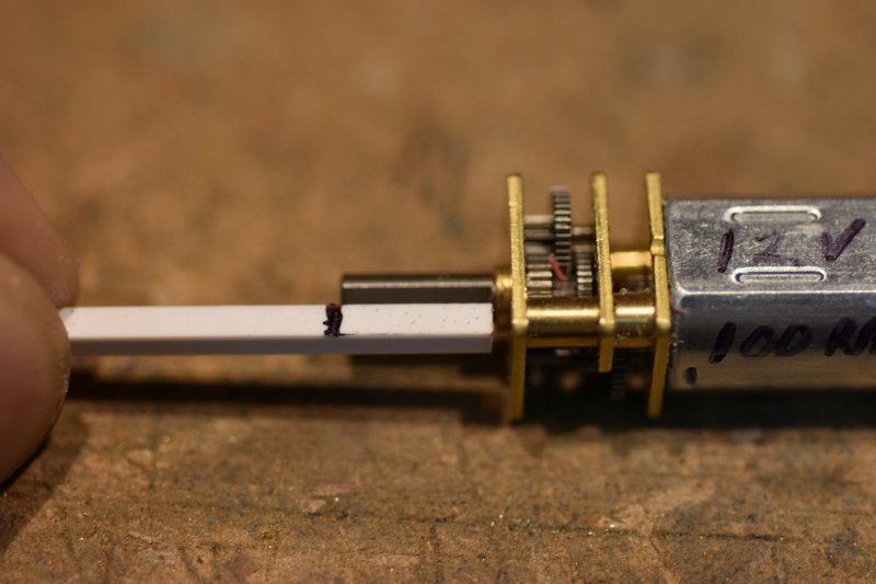 [/img] [/img]There are a number of ways to cut back the hub, I used my small mill after clamping up the wheel/tire in a 3-jaw chuck. [img]  [/img] [/img]Then I would mill off a little bit of the hub, check the remaining length with the gauge. Kept repeating this until the mark on the gauge was fully exposed. [img] 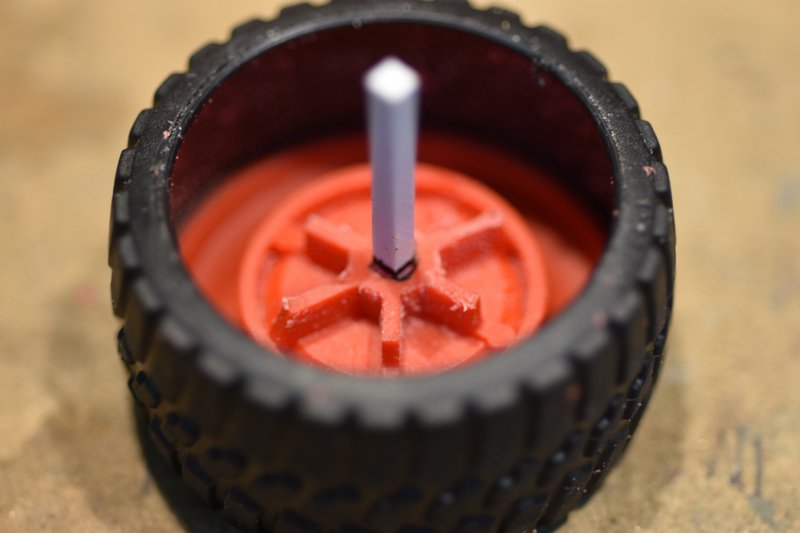 [/img] [/img]This ensured that the remaining hub was just slightly shorter than the length of the motor shaft and would not rub against the gear box. The tire ended up being almost completely centered under the servo shaft. It's just a little off but not enough to be a problem. If you want it to be completely centered then you could remove a little bit off the end of the drive shaft and shorten the hub just a little more. If you try and drill the hub a little deeper I think you have a good chance of just drilling right through the front of the hub which would ruin the looks. I didn't think it was worth the bother to do. As mentioned above the motor shaft is a loose fit into the wheel hub. Since the original axle was pretty much a friction fit I figured that would work here as well. There is a flat on the motor shaft and I used CA to secure a thin strip of styrene on it. [img] 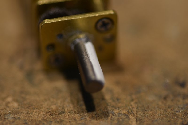 [/img] [/img]After the glue cured I carefully sanded the plastic down until I got a nice snug fit of the hub over the drive shaft. [img] 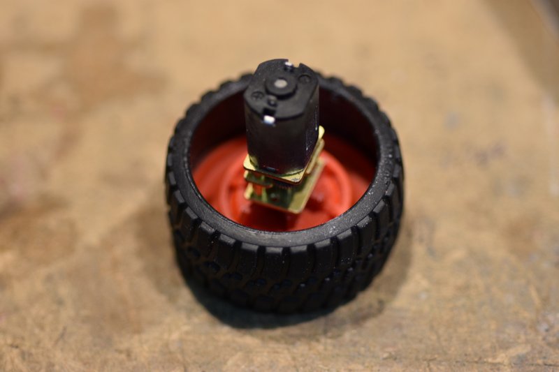 [/img] [/img]Soldered the power wires to the motor and inserted the motor into the support arm. [img] 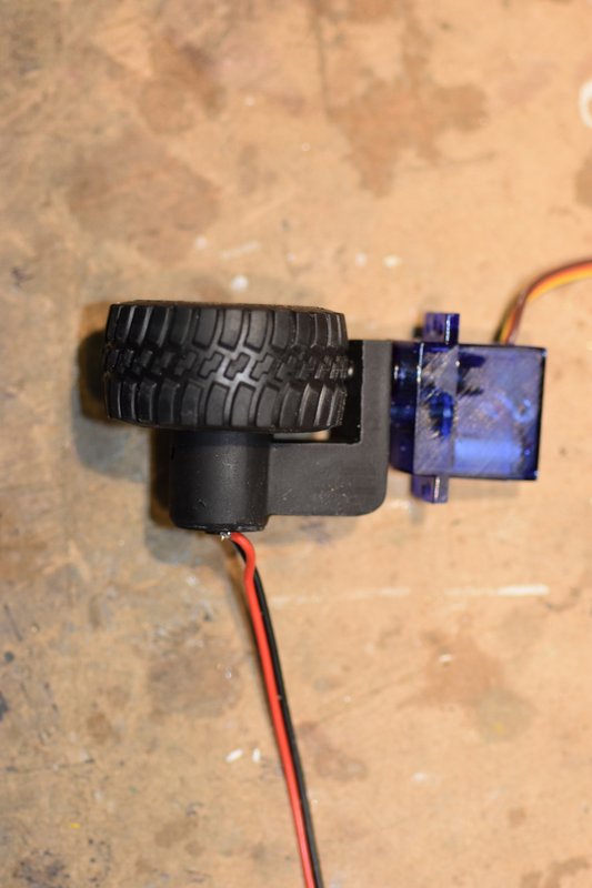 [/img] [/img]On one side of the support arm is a groove. I used this to route the power wires around the back side of the arm. To hold the wires in place I used a few tiny eye screws. These are used to hang pictures and are available in craft stores. [img] 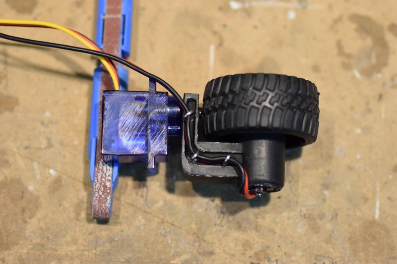 [/img] [/img]I then installed the assembly into the mounting plate installed earlier. The servo has to be inserted from the bottom at an angle and then rotated into final position. I was able to do this as a complete assembly but you could also just insert the servo first and then attach the arm and then insert the motor [img] 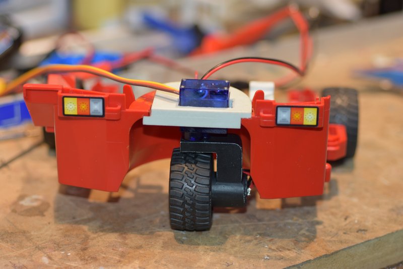 [/img] [/img]Next was to hook it up to a battery and receiver and test the functioning. It worked well but only turned 90 degrees left and right. Well that's the 'normal' range of motion on typical servos. The real world forklifts like this though are capable of ZTR or Zero Turn Radius. That's what I wanted for this model also. The classic fix to get more rotation is to take the servo apart and insert a couple of resistors into it's potentiometer circuit. Yea, that's a pain to do in a standard size servo. I really didn't want to try on a micro servo like this. Fortunately I was using a new Radiomaster TS16S transmitter for this build. It allows me to extend my endpoints out to 150% so I could get more servo rotation without having to modify the servo. It won't get me all the way to a full 180 degrees but it's close enough. [img] 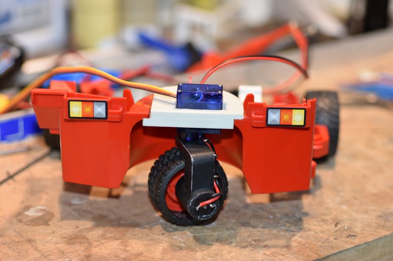 [/img] [/img][img] 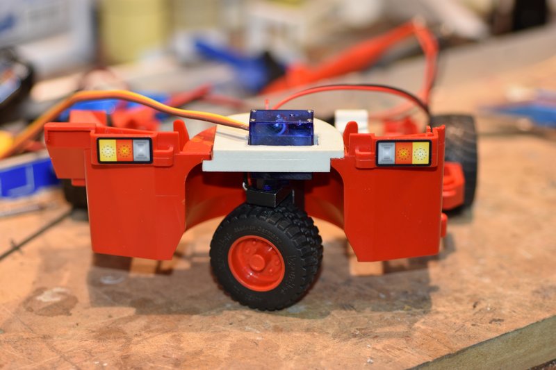 [/img] [/img]That's all for this post. In the next I'll start in on the lift mast.
|
|
| Currently Active Users Viewing This Thread: 1 (0 members and 1 guests) | |
|
|


 Hybrid Mode
