|
|||||||
| Highway Trucks and Trailers On road trucks and trailers single and twin axle trucks. |
 |
|
|
Thread Tools | Display Modes |
|
|
|
#1
 09-08-2021, 02:20 PM
|
|||
|
|||
|
Bruder Piggyback Forklift Build part 8
The last mechanical assembly that needs to be installed is the servo and linkage to move the lift mast assembly in and out. The original poster of the Thingiverse conversion parts used what some refer to as a wing or aileron servo. They are designed to fit in narrow places like wings. These servos are narrower than conventional servos and have their mounting flanges sit flush and parallel to the back of the servo instead of being perpendicular to the back. He designed his servo mount accordingly. I didn't have any of these servos on hand so decided to see if I couldn't fit a standard mini servo into the same space. After some measuring I determined that I could. But how to mount it? I could make a mount similar to the Thingiverse part but with a top screw hole for one end and a second mount to attach somehow to the curved wheel well housing wall on the other end. That would be tricky and could obstruct the ability to run wires through that area later on. After studying the shape of the servo I wondered if it wouldn't be possible to make a mount that only used one screw for one end of the servo and then wrap around the round portion of the servo and keep it from moving side to side under load. After making up a couple of trial mounts I came up with the design I finally used and it seems to work well. The photo below shows the servo mount from Thingiverse on the right and my mount on the left. [img] 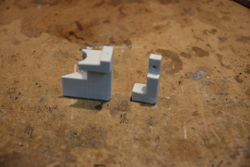 [/img] [/img]The mount fits into the lower body as shown below. [img] 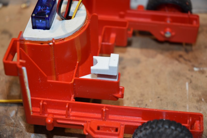 [/img] [/img]I drilled a couple of holes up through the bottom of the body and into the mount to secure it with screws. NOTE: The mount needs to be turned 180 degrees from shown for proper orientation, I wasn't paying attention when I took this photo. Also the photo shows round head screws again. Don't use them. [img] 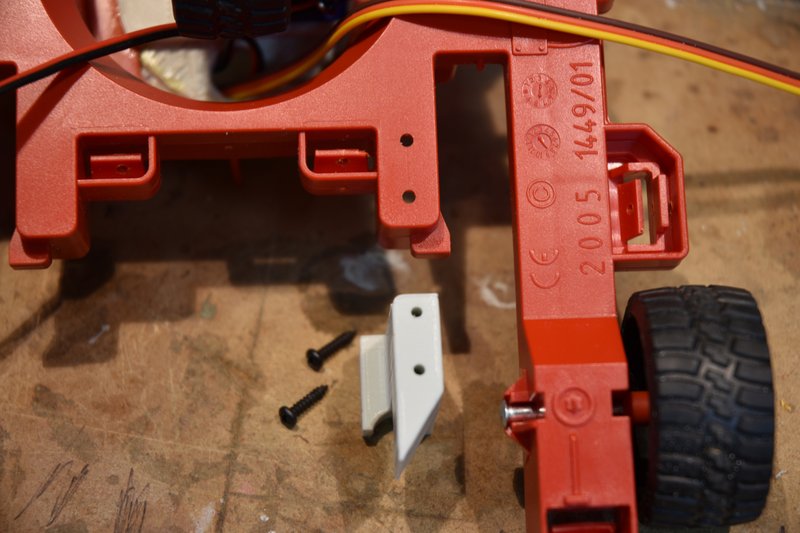 [/img] [/img]You must use flat head screws here or the lift mast assembly will not be able to slide past! Yea, after all this time I finally broke down and bought some flat head screws. ****, I bought hundreds so I won't have this problem ever again. [img] 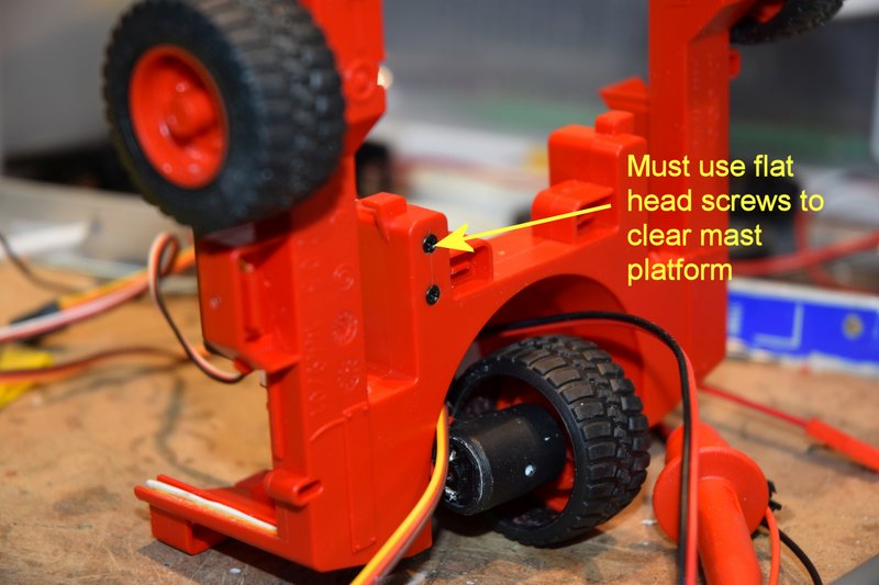 [/img] [/img]The next photo shows how the servo fits in the mount. When I first installed the servo I used a standard flanged head mounting screw that came with the servo. I found though that the flange would not clear the inside of the top body section when I tried to lower it in place. [img] 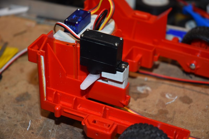 [/img] [/img]If I removed the flange or used a smaller screw I did not think the servo would be held securely enough as the mounting hole on the servo is larger than the screw so that a rubber vibration isolater can be used. Don't need the isolator in this case and I wanted the servo mounted solidly. So I cut off a short length of plastic rod and center drilled it to make a bushing to take up the excess space. [img] 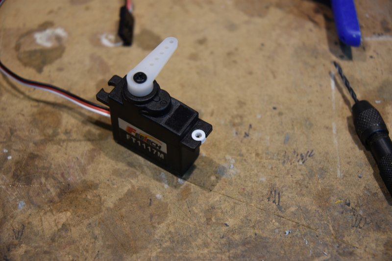 [/img] [/img]I then cut and drilled a piece of brass bar stock to use as a clamp across the entire width of the servo's mounting flange. This photo shows the final mounting. You can see that I also started to remove some of the internal plastic. [img] 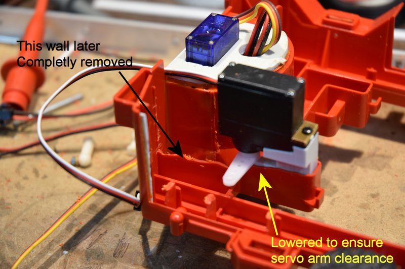 [/img] [/img]I again used ball connectors to make up the linkage between the servo and lift mast base. I used Tamiya 4mm balls and connectors just like the ones used in their truck kits. You can buy these direct from Tamiya but be aware that they refer to them as 'adjusters'. I mounted one ball on the end of the longest servo arm that came with the servo and oriented it pointing down as installed on the servo. The ball for the lift mast base was mounted as shown. Exact placement is not critical. There isn't room on the underside to install a nut so the hole I drilled for the ball was undersized and then I forced the threads to cut their way through the plastic as I installed the ball. [img] 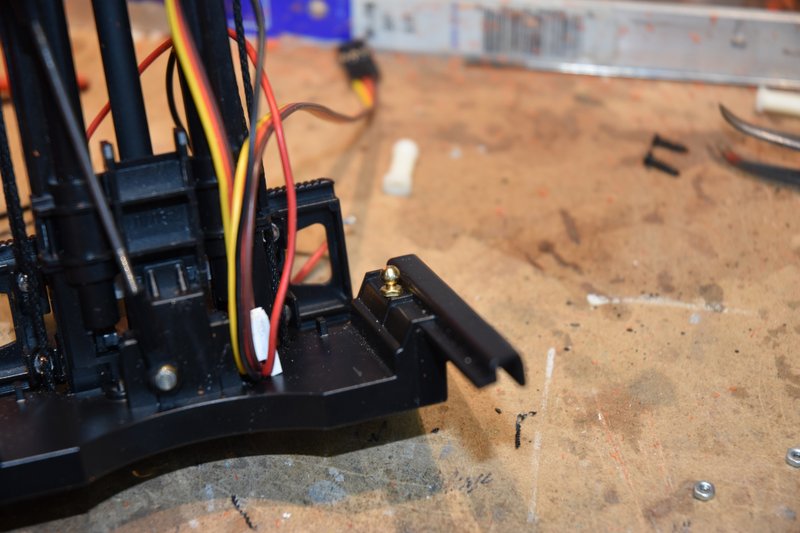 [/img] [/img]Because there was not a nut on the backside of the ball connector I was a bit concerned about it eventually working itself loose. So I mixed up a small amount of 2 part epoxy and poured it into the cavity where the screw thread was and embedded it. [img] 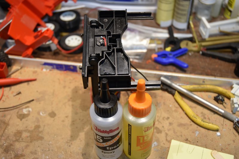 [/img] [/img]And here is the linkage to connect the two balls together. Note that I cut the threaded ends of the connectors back a bit. I did this to make it a bit easier to make length adjustments if needed without having a lot of friction to fight. [img] 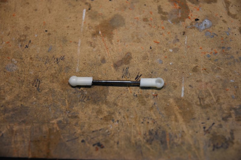 [/img] [/img]And that's pretty much it. In this photo you can see how the servo fits inside the body. There is still quite a bit of room left for a battery pack. In this photo the servo is shown in its neutral position. [img] 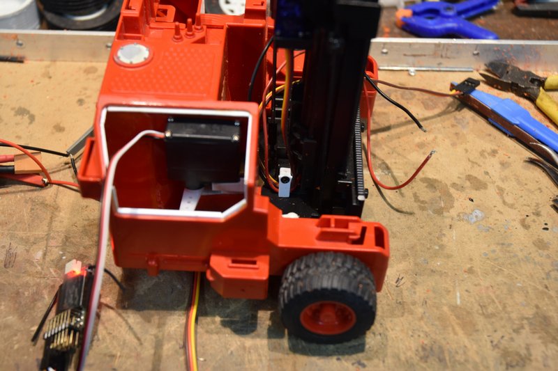 [/img] [/img]Like the steering servo, I needed more servo arm movement than the standard 90 degree left/right. One option would be to install a longer servo arm but that might start causing clearance problems. Or I could install resistors in the servo to increase it's range. Maybe a little easier to do in a mini servo as opposed to a micro servo but not what I wanted to do. Again I was able to open up the set points on my transmitter for this channel to 150%. That gave me enough linkage movement to be satisfactory. This photo shows the mast in it's full forward position. [img] 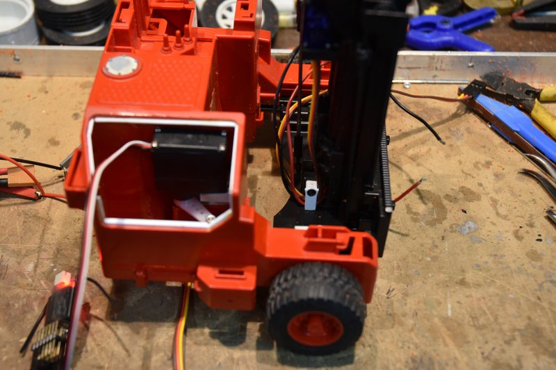 [/img] [/img]The mast assembly could be moved forward a bit more but as long as the back side of the forks would clear the front of the body I was satisfied. You can see that the mast itself is now in front of the center of the front wheels. Those wheels are the fulcrum for a lever and the further ahead the mast gets the easier it becomes to tip the forklift over. This last photo shows the mast fully retracted. [img] 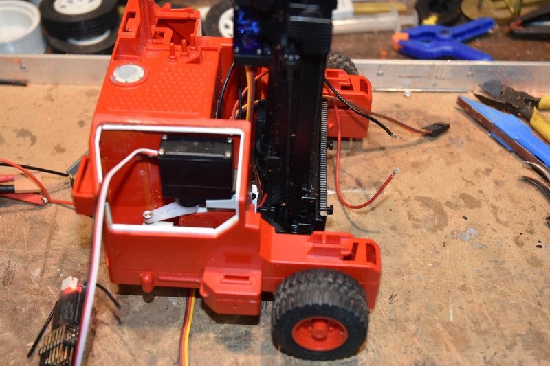 [/img] [/img]Again the mast assembly has room to move back a bit more. But some room is needed at the back of the mast base to allow the tilt servo cable and lift motor wires room to move. I may, after more operational experience, shorten up the link rod between the servo and the base plate. This would shift the entire lift mast assembly backwards. I have more front extension then really needed and it would move the mast further behind the front wheels increasing the amount of weight that could be lifted without tipping. We'll see. That is all the mechanical adaptations that need to be made to make this model operational. In the next post I will address two other small items before we get into how to stuff 10 pounds of electronics into a 5 pound sack. 
|
|
#2
09-09-2021, 02:03 PM
|
|||
|
|||
|
Bruder Piggyback Forklift Build part 9
A couple of things to take care of before tackling the electronics. First, if you look back at the last few photos in the last post you see the open area in the body where the battery pack needs to go. You also see that there is the servo and linkage that moves the lift mast assembly in and out. We don't want the battery to hit or obstruct this linkage. So some kind of barrier needs to be made and installed to prevent this. I choose again to use brass but plastic or even wood could be used here as well. I measured the height from the inside bottom of the lower body to the top of the nut holding the ball connector on the servo arm and added 1mm. I just dug out some scrap square tubing and flat plate from my scrap box, cut to size and soldered up the parts as shown below. [img] 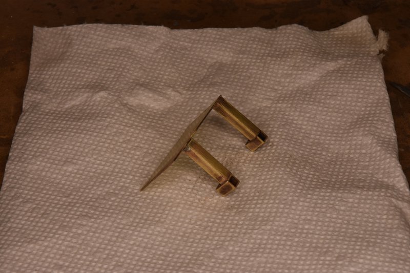 [/img] [/img]The piece fits into the lower body as shown. The 'feet' on the bottom were sized to fit between the outside wall and a rib in the bottom. [img] 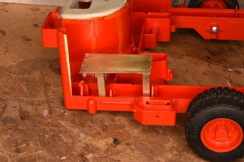 [/img] [/img]Here's another view from a different angle so you can see a little better how the feet fit in. They were drilled for #2 screws and matching holes drilled in the bottom of body. [img]  [/img] [/img]And here's a view of the bottom showing the mounting screws. Yep, flat head screws now, I finally learned although it doesn't really matter here as there is nothing that needs to move past these screws. [img]  [/img] [/img]I actually did this part of the build early on which you might be able to tell from the photos. I did this so I could get a better ideal of just how big a battery pack I would be able to fit in. I had originally planned on using a 3S lipo. However the quality of the small ESCs that would work on 3S I discovered are horrible. They either have no real low voltage range to them or they blow out after a few seconds. They all come from China and they must all be made by the same company as it doesn't matter who you get them from they all look alike. I finally decided to try 2S battery and ESCs. This worked much better. I found some ESCs that claimed to be a new design and had a big capacitor hanging off one end. So far they have worked and held up well. The battery I finally settled on is made by a company called SPC Maker. It is 2S and rated 500mAh. It is primarily marketed to the racing drone group. It measures approximately 50x25x13mm and fit in the available space very nicely. And while it looks awfully tiny compared to the size of the batteries we normally use in our trucks and construction equipment I find that I can get a good solid hour of continuous operation out of it, which is plenty for me. The last thing to be addressed before assembling all the RC electronics is the warning light on top of the ROPs. I didn't put any other working lights on my model but I did want that light to flash. This is a real simple conversion. I used a LED that had it's flashing circuit already built it. These are available from a number of sources, mine came from Eflite. It also included the necessary over-current protection resistor already installed. Photo below shows the light fixture and the LED. [img] 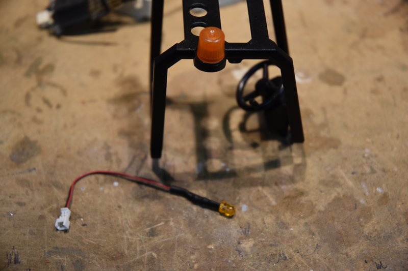 [/img] [/img]I cut the socket fitting on the end of the wire off so I could add additional wire to the LED. Also if I had left it on I would have had to cut a much larger hole in the body to pass it through to the inside. To remove the lens, just grab it and twist while pulling up. Mine came right off. Drill a 3mm hole right through the middle of the circle as shown. [img]  [/img] [/img]There is a lug in the center of the lens that needs to be cut back some so it will sit down on top of the LED. Don't remove it completely as it will act as a light pipe make the lens appear brighter when the LED is lit. [img]  [/img] [/img]I glued the LED into it's mounting hole from the bottom using CA. After it cured I then bent the wire to follow the inside of the ROPs cage and CAd it in place. [img]  [/img] [/img]Then the lens was glued back in place over the LED. To prevent possible fogging of the lens from CA I used a watch crystal cement. The last step was to hold the ROPs in postion on the upper body and mark the location of the notch for the wires from the LED to enter the body. [img]  [/img] [/img]I crimped a couple of female connector pins to the ends of the LED wires. When installed these will just plug onto the positive and negative pins of the battery port on the receiver. When the receiver is powered up from the BEC of one of the ESCs it will also turn on the flashing LED. At this time all the modifications are pretty much complete. I had tested each individual servo and motor system as it was installed. Now everything was hooked up and run though it's paces. I was very relieved to find that everything worked as it should. The model was stripped back down and sent to paint. I won't bother with showing any of that, painting is painting. Next post I'll start in on the 3d version of Tetris and figure out how to cram everything into the available space.
|
|
| Currently Active Users Viewing This Thread: 5 (0 members and 5 guests) | |
|
|


 Hybrid Mode
